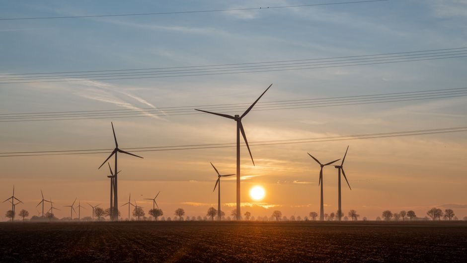
A 20 MW floating offshore wind turbine rolled off CRRC's Sheyang, Jiangsu line on 10 October 2024, with a swept area equivalent to more than seven standard football fields and a rated output of 20 MW per unit [S2].
The Sheyang milestone frames 2026-era production line design around three decisions: which turbine class the line is dedicated to, whether the line accepts a fixed-bottom or floating platform, and how much of the load and aero-elastic verification is pushed upstream into simulation [S2][S1].
Capacity Target and Module Boundaries
Lines built for 10-20 MW units are now sized around rotor + drivetrain + tower + (optional) floating sub-assembly cells rather than the old single-cell "monolithic" bay [S2]. CRRC's Qi hang design explicitly adopts a modular unit/function/platform split, allowing optional power levels, base types, and floating platform selection on the same family [S2]. For process engineers, this means each cell carries its own tooling, lifting capacity, and test rig, and the takt time is set by the heaviest module (typically the nacelle at 10-20 MW) rather than by blade layup.
Bay sizing follows the swept-area and blade-tip-speed envelope, not just rated power: Qi hang's blade tip speed reaches high-speed-train territory, which forces closed-loop pitch-test rigs and oversize balancing pits inside the nacelle cell [S2]. For comparison, a 3-5 MW line tolerates a 60-80 t overhead crane in the assembly bay; a 20 MW line typically needs 250 t+ with dual-hook synchronization to keep the hub-nacelle interface within tolerance.
Simulation-First Engineering Workflow
DNV's Bladed software computes horizontal-axis wind turbine loads and performance, with deep validation against field-measured turbines, and offers a Bladed API to automate calculation setup inside a customer workflow [S1]. For lines that ship floating units, Bladed couples to DNV Sesam for the offshore structural side, and the same load cases are then re-used by Ansys Mechanical / Fluent for blade aerodynamics, structural fatigue, and thermal maps on the generator and converter [S1][S3].
Three concrete workflow gates sit on top of those tools: (1) a DLC (design load case) matrix locked in Bladed before any steel is cut; (2) Ansys Icepak thermal envelopes for the nacelle, with cooling-duct geometry iterated until bearing temperatures stay inside the grease limit; (3) a digital twin thread that hands load spectra and controller gains downstream to the wind turbine control and instrumentation loop [S1][S3]. Engineers should not let the simulation chain run as separate silos - the API hook is what converts a simulation study into a production line spec.
Floating Sub-Assembly and Quay-Side Integration
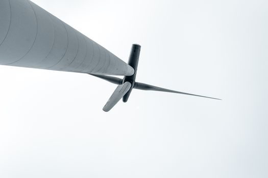
Floating production lines split the build into a land-based turbine assembly cell plus a quay-side mooring/semisubmersible integration cell, because the floater cannot be moved overland once ballasted [S2]. Springer design-optimization work on floating substructures treats global limit states, geometric dimensions, and mooring stiffness as one coupled problem, which is why a CRRC-class 20 MW floater needs a separate wet-storage basin and a wet-tow-out lock [S5].
The line-side consequence is that tower, nacelle, and blade pre-assembly must be scheduled to a moving floater, not to a fixed station. Cell layouts for floating work therefore use a "moving cathedral" pattern: turbine modules converge on the floater, are mated, and the integrated unit is then wet-towed to the cable-lay vessel. This drives longer work-in-process (WIP) and higher buffer stock between cells than a fixed-bottom line of equivalent nameplate capacity.
Quality, Standards, and Source-of-Truth Documents
Design load cases, type certification, and component qualification flow from IEC 61400 (wind turbine family) and its sub-parts; control design for variable-pitch turbines is documented in established textbooks on gain-scheduling control [S7]. The 2026 sourcing and spec map is laid out in the wind turbine quality standards reference, which catalogues which sub-component (blade, bearing, converter, tower flange) maps to which IEC/ISO clause and which supplier tier is qualified.
For engineers choosing simulation vendors: Bladed is the load-and-performance reference with the deepest field validation and direct DNV Sesam hand-off for offshore structures [S1]; Ansys is the broader multi-physics stack covering Fluent, Mechanical, and Icepak for blade, drivetrain, and nacelle thermal work [S3]. The two are complementary, not substitutes - locking load cases in Bladed first and re-running detailed fluid/thermal cases in Ansys is the current 2026 norm for a 10-20 MW design office [S1][S3].
Cost, Supply Chain, and Where the Line Gets Stuck
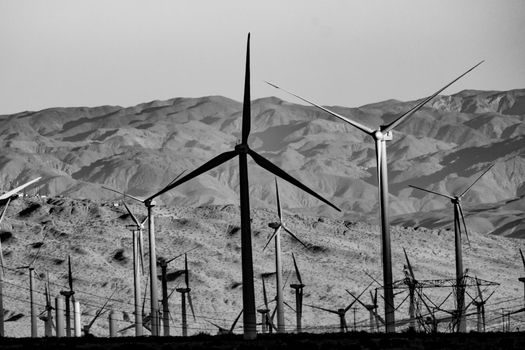
Cost breakdown for the turbine itself (not the line tooling) is dominated by blade, tower, drivetrain, and converter, and the per-kW figure moves sharply with module standardization - a point detailed in the wind turbine manufacturing cost reference. The production line bottleneck, however, is usually not in any single one of those parts; it is in the interface between the blade cell and the hub-bolt cell, where torque-angle-QR records must be retained for the full type-certification file. [S2]
The other repeat-failure hotspot is gear reducer installation: foundation flatness, laser alignment, oil-flush cleanliness, and run-in loading all gate the nacelle cell output, as documented in the helical gear reducer installation guide. Industry 4.0 traceability (IEC 61400-25 condition monitoring, RAMI 4.0 digital twins) is the lever that converts those gates from a paperwork problem into a line-side dashboard - the rollout status is tracked in the wind turbine Industry 4.0 adoption brief.
Track three signals over the next two quarters: (1) whether 15-20 MW dedicated lines reach a published takt time below 48 hours per nacelle, (2) whether floating-integration yards announce a second wet-tow-out lock, and (3) whether IEC 61400-25 condition-monitoring data from new fleets is fed back into Bladed DLC matrices for the next platform revision [S1][S2].
For component-level specifications, see turbine flowmeter, molding line, and automatic molding line.