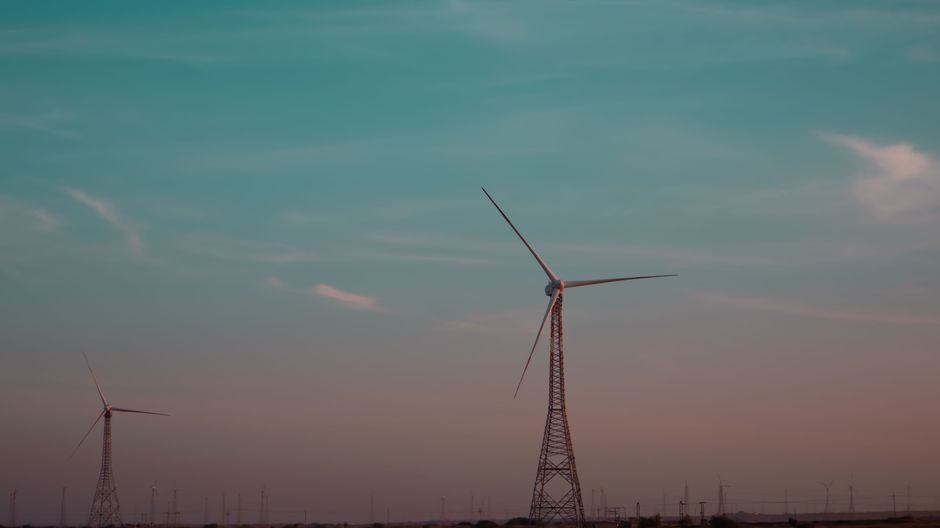
A utility-scale wind turbine is a continuous-control asset: a main PLC/PAC runs pitch, yaw, generator torque, and grid-synchronization loops at 50–100 Hz, while a SCADA layer aggregates 50–300 tags per turbine and pushes them up to the park controller over IEC 61400-25 [S5][S2].
Instrumentation is split between the tower base (controller, grid-side MV switchgear, condition-monitoring server) and the nacelle (pitch motors, yaw drives, gearbox, generator), with fieldbus traffic dominated by CAN, PROFIBUS, and increasingly EtherCAT or PROFINET between the controller and the pitch/yaw drives [S1][S2].
Control Architecture and Communication Standards
The pitch loop runs individual servo drives on each blade, with the main controller closing position and rate loops at roughly 50 Hz and demanding deterministic, real-time communication [S1]. The yaw loop drives the nacelle to keep the rotor aligned with the wind direction, with cumulative untwist error monitored through the nacelle-position encoder; field installations commonly use Fuzzy-PID combined control to suppress overshoot in turbulent inflow [S1].
Park-level communications rely on IEC 61400-25 (the wind-specific mapping of IEC 61850 / 61850-7-4 logical nodes) for status, metering, and analog values, with OPC UA increasingly added for condition-monitoring data exchange to the OEM cloud [S2]. For the tower-base grid interface, differential protection of the stator-ground fault path on full-converter turbines is a recognized requirement, and the converter itself is treated as a controlled current source on the grid side rather than a voltage source [S2].
Generator and Drive-Train Loop Choices
The two dominant topologies are the doubly-fed induction generator (DFIG) with partial converter and the permanent-magnet generator (PMG) on a full-converter back-to-back, with a documented reliability gap between the two architectures that any process-control spec should resolve on a per-site basis [S2]. Variable-speed constant-frequency (VSCF) operation is the default for both, with soft cut-in to limit inrush at grid connection and to keep torque transients inside the gearbox rating [S1].
Sensor count on the drive train is heavy: a PT100 / 4-wire RTD on each generator bearing and winding phase, vibration probes on the main bearing and gearbox, and a passive speed sensor on the shaft feeding a phase-locked loop for the converter's rotor-position estimate [S2][S3]. Extended Kalman Filter state estimation is the documented academic baseline for fusing these measurements into a single observable state vector covering rotor speed, generator torque, and wind speed [S3].
Sensor Stack: What Gets Measured Where
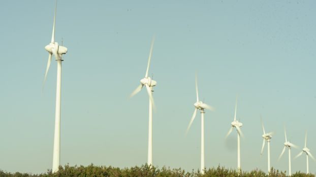
Pitch and yaw systems rely on absolute encoders (typically SSI or CANopen) for blade angle and nacelle position, with redundant position feedback on each blade to satisfy safety-integrity requirements on the pitch loop [S1]. The pitch cabinet itself contains the servo drive, an emergency-power backup (super-cap or battery) capable of feathering the blades under loss of mains, and pitch-motor thermal protection [S1].
For the process side, the loop-list read-back is dominated by the anemometer on the nacelle (cup or sonic), a wind-vane for direction, the main-shaft torque transducer, gearbox oil temperature and pressure, hydraulic-pitch pressure, and tower-top / tower-base accelerations for structural load monitoring [S2][S3]. Strain gauges on the blade root and tower base are standard on turbines above roughly 2 MW for load reduction and lifetime-extension control, and feed the individual pitch-control loop that asymmetrically pitches each blade to mitigate asymmetric loads [S2].
Condition Monitoring, Failures, and Where the Process Loop Sits
A standardized 2021 review of wind-turbine failure data identifies the gearbox, blades, pitch and yaw systems, and generator as the highest-failure subsystems, with control-system and sensor faults making up a smaller but operationally significant share [S2]. Gearbox bearing loading during transient events is specifically called out as a dynamic-loading concern, not a steady-state one, which pushes the choice toward high-bandwidth vibration and oil-debris sensors rather than temperature alone [S2].
Condition-monitoring economics, not just the sensor spec, drive what gets installed: gearbox replacement on an offshore turbine can run into the low-millions, so a multi-sensor condition-monitoring package (vibration + oil-particle + oil-moisture) typically pays back well inside the gearbox design life [S2][S4]. Cost figures from published wind-energy economics place operations and maintenance in a double-digit-percentage band of levelized cost of energy, with the bulk attributable to the access, crane, and vessel cost when a major component fails, which is the reason CM is treated as a process-control input rather than a diagnostic afterthought [S4].
Selection Criteria, Limits, and Who This Is For
For a new build, the controller choice is straightforward: a PLC or PAC with IEC 61131-3 languages, redundant processor on offshore units, and an HMI that exposes the standard wind-power logical nodes defined in IEC 61400-25 [S5]. For brownfield retrofits, the constraint is the existing fieldbus, and most WT1650-class controllers communicate on CAN with the pitch and yaw cabinets, so any new condition-monitoring server has to read from the same bus [S1].
The architecture is not for everyone: small sub-100 kW turbines often run a single embedded controller with hard-coded pitch and yaw loops and no external SCADA, while turbines above roughly 3 MW always use a separated pitch cabinet, a separate yaw drive, and a park-level controller in the tower base [S1][S2]. Anyone designing the loop-list should also plan for the safety chain as a hard-wired loop independent of the main PLC: over-speed, vibration-trip, and grid-loss contacts run as a failsafe series, with the pitch system reverting to feather under loss of hydraulic or electrical power [S1].
Comparison: DFIG vs PMG vs Squirrel-Cage on Control Burden
For process-control complexity, the three drive trains sort cleanly: the DFIG needs a rotor-position encoder, slip-ring slip monitoring, and a partial-scale converter, but the grid-side behaviour is partly governed by the stator and the converter is smaller; the PMG full-converter decouples the generator entirely from the grid, simplifying grid-fault ride-through and removing the need for a rotor-position sensor on the generator side, but it shifts all the control burden onto the converter's controller; the older squirrel-cage induction generator with a full-converter is a middle ground in complexity and is commonly specified for soft cut-in and asynchronous connection [S1][S2]. On a maintenance-load basis, the reliability comparison in the literature shows a measurable, architecture-dependent gap between DFIG and PMG drive trains, which translates into different mean-time-between-replacement figures on the generator and converter [S2].
Sourcing, Standards, and Field Reality
Specifying engineers should anchor the loop-list to IEC 61400-25 for park communications, IEC 61850 for substation and grid-side data exchange, and IEC 61131-3 for controller programming language; for safety, the pitch-system safety chain is typically designed to a risk-reduction target that yields a hard-wired safety loop independent of the main controller [S5]. On the inspection side, the turbine flowmeter spec and any multifunction process calibrator used for loop commissioning are unrelated to the wind loop itself, but the same calibrator discipline applies to the wind vane, anemometer, and torque-transducer verification on the bench before tower erection.
For broader context on park-level planning, the wind turbine capacity planning: formula, zoning, and spec gates piece covers the siting and spec-gate side that precedes the loop-list decision. For pitch and yaw drive-train mechanical gates that the controller has to protect, the RV reducer installation: bolt torque, shaft seating, lubrication, and run-in gates article is the matching mechanical reference.
Component reference pages worth checking: v process line.