
Single-stage worm reducers cover 5:1 to 100:1 ratios, with self-locking tendency emerging above 60:1, making them the default drive for conveyors, hoists, and turntables in material handling [S1][S2].
Efficiency is the real selection constraint: a 5:1 unit runs at 85–90% mechanical efficiency, while an 80:1 unit drops to 35–52%, which converts input torque directly into heat rather than output work [S1]. Frame size, service factor, and thermal rating therefore decide the part number, not the ratio alone.
Ratio Range and Output Speed for Typical Material Handling Loads
Most material handling applications run with 1,400–1,450 rpm 4-pole motors, so the output speed of a 50:1 worm reducer lands at roughly 28–29 rpm, a common value for conveyors, feeders, and indexing tables [S1][S2]. Faster driven shafts such as small packaging conveyors or transfer auxiliaries typically use 10:1 to 20:1 ratios, which deliver 70–145 rpm output at 1,400 rpm input and still avoid the efficiency cliff [S2].
Very slow positioning axes on palletizers and rotary turntables routinely select 60:1 to 100:1 single-stage units because self-locking holds the load when the motor de-energises, removing the need for a separate holding brake [S3]. The trade-off is efficiency: a 60:1 unit sits at 42–58%, so roughly half the motor input ends up as casing heat that must be rejected through the housing or an external fan.
Torque, Efficiency, and the Heat Penalty
Output torque equals motor torque times ratio times efficiency, not ratio alone: a 60:1 worm gearbox at 55% efficiency driven by a 10 Nm motor delivers 330 Nm, not the 600 Nm implied by the ratio [S1]. The lost 270 Nm is dissipated as heat in the gear mesh, which is why undersized worm reducers fail thermally long before they fail mechanically on conveyors that run continuously.
For uniform loads on belt conveyors, service factor 1.0 is acceptable, while moderate shock applications such as bucket elevators or reversing mixers need 1.25–1.50, and heavy shock loads from crusher feeders or crane slewing drives need 1.75–2.0 multiplied onto the calculated torque before frame selection [S1]. Standard catalogue ratios from 5:1 through 80:1 are stocked by most suppliers, so non-standard ratios should be avoided for material handling lines where spares lead time matters.
Self-Locking Behaviour and Where It Matters
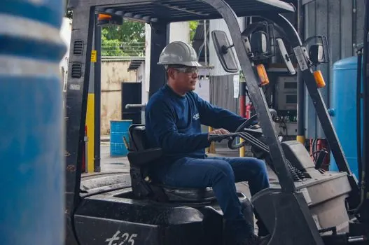
Self-locking tendency rises with ratio: 5:1 to 10:1 units back-drive freely, 15:1 to 30:1 show low tendency, 40:1 to 50:1 show high tendency, and ratios of 60:1 and above are very high and effectively prevent back-driving under normal load [S1][S3]. This is the property that makes worm drives the default for forklift mast lifting, hoist holding, and inclined conveyors where a power failure must not drop the load.
For an overview of the broader drive family, see the worm reducer selection guide. When high ratio plus high efficiency matters more than self-locking, a helical-bevel arrangement typically wins, but it adds length, cost, and an external brake for vertical lifts [S1].
Flange Mounting, Service Factor, and Motor Interface
Flange mounted worm gear reducers bolt directly to IEC or NEMA motor frames, eliminating couplings and achieving shaft concentricity within 0.05 mm without additional alignment hardware [S4]. The rigid flange interface raises torsional stiffness, which reduces vibration transmission into the conveyor frame and extends bearing life in continuous-duty plants.
Selection order on a flange unit is straightforward: calculate required output torque and ratio, apply the service factor for the load class, then verify flange size, motor interface standard, IP rating, and housing material against the operating environment [S4]. For dust-laden aggregate handling or washdown food lines, IP65 minimum is common, while indoor parcel conveyors typically run IP54. Material handling drive selection also requires checking how the unit fits into the broader conveyor system, covered in the material handling equipment reference.
Noise, Vibration, and the Sliding-Contact Reality
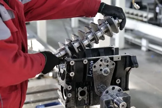
Worm gear meshes are sliding contacts, so noise and vibration are governed by gear geometry, lubrication film, alignment, bearing play, and housing stiffness, not by the reducer alone [S5]. Common root causes include profile errors from poor hobbing, low-viscosity lubricant that collapses the film at high contact pressure, excessive backlash that shocks at direction reversal, and resonance in thin housing walls.
Practical noise control means stable contact patterns through precision worm and wheel sets, lubricant viscosity matched to load and surface speed, bearing preload checked at installation, and a housing geometry that avoids amplifying the gear-mesh frequency [S5]. In packaging lines, where the same supplier's worm reducer family is also used on form-fill-seal machines, similar rules apply, as detailed in the worm reducer sizing guide for packaging lines.
Worm vs Helical-Bevel for Heavy-Duty Material Handling
Worm reducers win where high single-stage ratio, right-angle output, and self-locking are needed in a compact envelope; helical-bevel reducers win where continuous-duty efficiency above 90% matters and a separate brake can be added for vertical hold [S1][S6]. On long overland conveyors and heavy-duty mining belts, helical-bevel drives cut heat buildup and power loss, so even at higher unit cost the lifetime energy saving offsets the premium [S6].
Decision rule for material handling: specify a worm reducer when the ratio is 30:1 or above, self-locking is desired, the duty cycle is intermittent, and the housing envelope is constrained; specify a helical-bevel when efficiency above 90% across the operating range is required and the duty cycle is continuous [S1][S6]. For the parallel mining use case, the worm gear reducer selection for mining tradeoffs article covers the dust, shock, and IP65 requirements in more depth.
Selection Criteria Compared: Worm vs Helical-Bevel in Material Handling
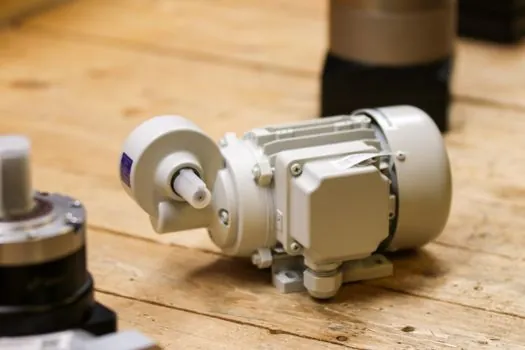
On the four criteria that drive the decision, worm and helical-bevel reducers line up as follows. Single-stage ratio: worm covers 5:1 to 100:1, helical-bevel typically 5:1 to 60:1 in one stage and stacks for higher. Mechanical efficiency: worm 35–90% depending on ratio, helical-bevel consistently above 90% across the ratio range [S1][S6]. Self-locking: worm provides it inherently above 60:1, helical-bevel needs an external brake. Footprint: worm is more compact in the radial direction because the output is at 90 degrees in a single housing.
For material handling, the choice usually maps to the load profile: conveyors with continuous run time benefit from helical-bevel efficiency, while hoists, lifts, and inclined conveyors that need passive load holding point back to worm drives [S3][S6]. Related storage and handling drive choices for warehouse and AGV applications are covered in the storage handling equipment reference.
The next practical step for any material handling selection is to lock down the duty cycle, ambient temperature, and IP rating before finalising the frame size, since those three numbers decide whether a stock catalogue unit is sufficient or a custom thermal configuration is required.