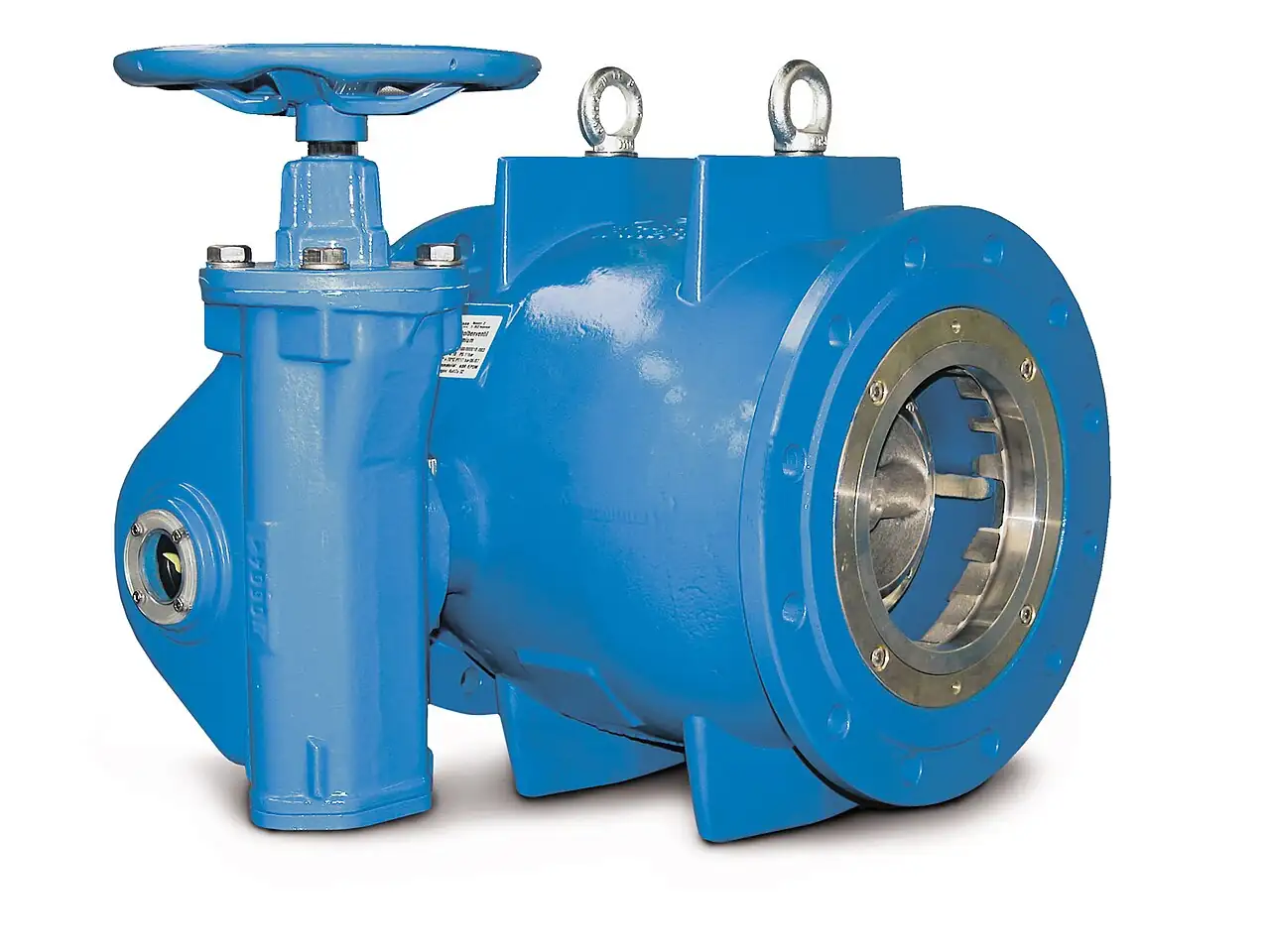
A choke valve is a restriction valve fitted between the wellhead and the flowline that takes a controlled, permanent pressure drop from upstream reservoir pressure to downstream pipeline pressure, holding back pressure on the well and metering production through a fixed or adjustable orifice. Two constructions dominate: the fixed choke, in which a tungsten carbide bean of a drilled size is loaded in a carrier, and the adjustable positive choke, in which a tapered needle unscrews from a seat across a calibrated travel range. Rotating multiple orifice cages add a third family for high capacity service. Working pressure ratings follow the API 6A series from 2,000 to 20,000 psi, and orifice sizes are spoken in 64ths of an inch, from 4/64 to 64/64.
Procurement engineers meet these valves on wellhead packages, well test spreads, and production flowlines: gas lifted oil wells, high pressure gas wells making condensate, sand prone completions, and sour service fields. The decision this page settles is narrow and practical: which trim family suits the well's behavior, how the bean or cage is sized against rate and pressure, and which API 6A package lines, working pressure, product specification level, material class, temperature class, end connection, and sour service qualification, the RFQ must carry. The answer lands as a line set the supplier can quote against and the site can maintain, and every chapter below feeds that line set so the choke is bought as a package rather than assembled from fragments.
This page treats the choke valve as a purchasing object: how fixed beans, needle and seat trims, and multiple orifice cages behave in choked and multiphase flow, what API 6A working pressure, PSL, material class, and temperature class lines actually commit a supplier to, how sand erosion is lived with rather than eliminated, and how the whole package is written into a defensible RFQ. It is written for engineers who issue purchase specifications for wellhead equipment, not for readers who want a brochure summary.
Chapter 1 / 06
What a Choke Valve Is and What Is Being Decided
The function is deceptively simple: pass production through a restriction small enough that the downstream line sees an acceptable pressure while the upstream tree keeps the well stable. Everything else about the valve follows from how violent that duty is. Pressure energy is destroyed in a few centimeters, gas flashes and accelerates, sand grit rides the stream, and the trim that shapes the jet is consumed by it. A choke is therefore bought as a set of wear parts in a pressure containing body: the body is ordered once against API 6A and lasts for decades, while beans, seats, needles, and cages are ordered by the box and replaced on condition. Specifiers who buy the body without pricing the trim consumption have bought half the valve, and the first well test will send the invoice for the other half.
What is actually being decided in this purchase is a package, not a part. The buyer commits to a trim family: a fixed bean for stable wells, an adjustable positive choke where rates are chased, or an orifice cage for high capacity. The buyer commits to the orifice range the well will need across its life, in 64ths of an inch for beans or stem travel for adjustable trims. And the buyer commits to the API 6A envelope: working pressure from the 2,000 to 20,000 psi series, product specification level 1 through 3G, material class AA through HH, and temperature class K through U. Sour fields add the NACE MR0175/ISO 15156 qualification line, and sand prone fields add the trim material decision, tungsten carbide or ceramic. Each of these lines is testable on paper at quotation stage, which is what this page exists to support.
Against its neighbors the choke occupies the high pressure letdown ground. Its trim ancestry runs through the needle valve of instrument benches and the metering globe valve of steam practice, and its body follows the angle pattern that an angle seat valve uses in utility service, but the pressures, the sand, and the codes are different in kind, and chapter 5 draws those boundaries carefully. It is not a general plant control valve: a modulating loop with a signal and a positioner is served by a globe control valve, not by a wellhead choke. Around it sit API 6A gate valves for isolation, the check valve and safety relief valve downstream that protect the flowline, and the instrumentation, a pressure transmitter each side, that tells the operator what the trim is doing. Stating the whole station in one RFQ lets one supplier check end connections, ratings, and trim schedules against each other instead of discovering mismatches on the wellsite.
Five documents organize the datasheet. API 6A and its ISO twin 10423 define the valve: working pressure series, nominal sizes, end connections, material classes, temperature classes, PSL levels, and the pressure and function testing behind every rating. NACE MR0175, identical in intent to ISO 15156, defines what sour service means for material selection. API RP 14E supplies the erosional velocity guidance used to reason about sand and high velocity service. API 16C governs the choke and kill manifolds that carry these valves on drilling rigs. A datasheet that quotes none of these is a price tag, because none of its ratings can be checked by the receiving inspector.
The station matters as much as the valve. Upstream, the wellhead master and wing gate valves isolate the choke for a trim change; a well test manifold usually carries two chokes in parallel, an adjustable unit and a fixed bean branch, selected by API 6A gate valves or a full bore ball valve so the operator can swap duty without shutting in. Downstream, the jet must be given straight, heavy wall pipe to expand into before the first elbow, and a target tee rather than a standard bend where sand is heavy. Instrument taps upstream and downstream carry a pressure transmitter each, because the pair tells the operator both the drawdown the choke is taking and whether the orifice has washed out. Flowline protection devices, the check valve and any pipeline safety relief valve, are specified with the choke rather than after it, so the whole pressure path arrives rated as one system.
Chapter 2 / 06
How Flow and Erosion Behave Through the Trim
Gas behavior dominates the physics. When the restriction is small relative to the pipe, static pressure at the vena contracta falls until the gas reaches sonic velocity at the throat: the flow chokes, and further reductions in downstream pressure no longer increase the rate. Choking begins when downstream pressure falls below roughly 0.5 to 0.55 of upstream absolute pressure for natural gas. Above that ratio the flow is subcritical and both pressures matter; below it, the rate depends only on upstream pressure, upstream temperature, gas properties, and the open orifice area. That is why operators state a bean change in 64ths of an inch at a given wellhead pressure and can predict the new rate on a critical flow well: the downstream line pressure barely features in the arithmetic.
Liquid and multiphase streams add damage mechanisms to the hydraulics. Pressure falls below the vapor pressure at the throat, gas flashes out of solution, and the mixture accelerates through and past the seat; droplets and any sand grains then impact the seat edge, the bean exit, and the first downstream wall at jet velocity. Sand is the killer: modest loadings of formation fines are enough to cut a plain steel orifice measurably within days, which is why flow wetted parts are tungsten carbide as the baseline and ceramics such as silicon nitride where velocity and sand loading are extreme. API RP 14E erosional velocity practice gives the reasoning frame, and every trim material decision in chapter 4 reduces to two honest questions: how much sand will the well deliver, and at what velocity will it arrive.
Temperature drops with the pressure. Real gas expansion through the restriction cools by the Joule Thomson effect, on the order of half a degree per bar of letdown for natural gas, so a 50 bar drop can arrive more than 20 deg C colder at the outlet, and rich gas with heavier components cools hardest. The consequences are practical and immediate: hydrates forming in and just downstream of the trim, water ice in wet gas, and thermal contraction loads on the downstream flange pair. Fields answer with methanol or MEG injection upstream, heated choke water baths on gas wells, and insulation over the first meters of downstream piping. A choke RFQ that never states an outlet temperature will be revisited on the first cold night of the season, usually from the hydrate blockage, not the valve.
Noise is part of the duty, not a defect. A choked jet dissipating tens of bar across a 12/64 bean is an aerodynamic noise source that can reach the 100 to 120 dB(A) class at close range before any cavitation from the liquid fraction adds to it. Well test packages put the choke in a barricaded or ventilated area with a defined hearing protection zone; permanent installations bury, barricade, or insulate the downstream run wherever personnel circulate. The engineering remedies are limited and honest: heavier downstream wall, buried pipe, distance, and trim styles that spread the expansion over more area. The purchase remedy is to treat the neighborhood of a producing choke as a designed noise zone in the plot plan rather than an incidental one discovered at commissioning.
The trim talks through the instrumentation. Upstream and downstream pressure, each read by a pressure transmitter, give the ratio that says whether flow is critical; the pair, trended against rate, shows orifice growth long before anyone can see it. A washed bean raises rate at constant upstream pressure, or forces the operator to close an adjustable trim further each month for the same rate, and that slow drift is the actual maintenance signal for trim replacement. Where the well is a candidate for automated optimization, the same measurements feed the controller that drives the actuator, which is how a manual choke becomes an actuated production choke managed from the control room instead of the wellsite.
Chapter 3 / 06
Types, Construction, and Duty Boundaries
The fixed choke is a bean in a carrier. The body carries a threaded or flanged bean carrier; the bean itself is a short tungsten carbide cylinder with a machined orifice, sized in 64ths of an inch, with catalog ranges running from 4/64 through 64/64, about 1.6 to 25.4 mm of diameter. The operator isolates, swaps the carrier or the bean, and returns the well to an exactly repeatable orifice, which is why fixed beans anchor well tests: the orifice does not creep with vibration, wear, or a handwheel bumped by passing traffic. The trim is consumed in place and replaced on schedule or on washout evidence, and the box of spare beans is part of the purchase, not an afterthought.
The adjustable positive choke is a needle and seat with a calibrated stem. A tapered needle, carbide faced, screws into or out of a carbide seat; the stem carries a handwheel and a position indicator graduated in 64ths of an inch equivalent opening, so the operator dials an orifice without breaking containment. The stem packing is the soft spot, a dynamic seal under full wellhead pressure that is greased on a schedule and eventually replaced. The same body accepts a hydraulic or pneumatic valve actuator with a positioner in place of the handwheel, which converts the manual choke into the actuated production choke used where the well is managed remotely or optimized continuously, and an electric actuator serves sites without instrument air or hydraulic power.
The multiple orifice cage spreads the drop across many holes. Two perforated cylinders nest one inside the other; rotating the inner cage changes how the hole patterns overlap, and with them the open area, while the stem stays out of the flow stream. The jet leaves as a ring of smaller jets instead of one concentrated one, which lowers the local velocity per hole, evens erosion around the circumference, and buys capacity, so cages appear on high rate wells and on automated chokes where continuous adjustment under actuation must survive. The multiple orifice cylinder family executes the same idea with drilled sleeves. The trade is complexity: more parts in the flow stream, more sealing surfaces, and a washout mode that is harder to detect by rate alone.
Construction follows the body pattern and the manifold. Angle bodies, inlet on one axis and outlet turning the flow, are the well test default because the jet expands into the outlet run instead of into an elbow; the same protective logic explains why an ordinary angle seat valve on a utility skid is angle bodied too. Straight bodies suit spool installations between flanges. End connections come from the API 6A menu: 6B flanges with R or RX ring gaskets for the 2,000 to 5,000 psi series, 6BX flanges with BX rings for 10,000 to 20,000 psi, and studded or clamp hub connections where makeup speed matters. Every choke needs isolation to change trim, normally an API 6A gate valve upstream, and drilling packages inherit the API 16C choke manifold architecture with its redundant branches and dual chokes.
The duty map below compresses the boundaries into a table a specifier can carry into a review meeting; it pairs well conditions with the trim that survives them and the shortcut that erodes into the next shutdown.
Service
Suitable construction
Construction to avoid
Well cleanup and initial test, sand at full load
Fixed choke with carbide bean, target tee downstream
Adjustable needle trim expected to survive the whole cleanup
Stable rate oil well on allocation
Fixed bean, quarterly orifice review
Cage trim bought for a well that never changes rate
Gas well under continuous optimization
Actuated adjustable choke or cage with positioner
Manual handwheel where the remote control link already exists
High rate gas well, wide turndown
Multiple orifice cage, ceramic inserts where sand carries
Small fixed bean run deep into critical flow at high velocity
Sand prone producer, extreme loading
Carbide or ceramic bean with a planned washout interval
The table below decodes the datasheet lines that decide whether a quoted choke matches the well. Each row is purchase defining; the paragraphs after the table explain what the API 6A lines actually commit the supplier to.
Body rating and the hydrostatic and function test behind it
Nominal bore
2 1/16, 2 9/16, 3 1/16, 4 1/16 inch common
Capacity envelope and manifold spool compatibility
Trim family
Fixed bean; needle and seat; multiple orifice cage
How rate is set and how trim wear is managed and detected
Bean and seat material
Tungsten carbide baseline; ceramic for extreme service
Washout life in sand and high velocity duty
Product specification level
PSL 1, 2, 3, 3G, 4
Depth of nondestructive examination and traceability behind the rating
Temperature class
K minus 59 to 82; L minus 41 to 82; P minus 18 to 82; U minus 18 to 121 deg C
Seal and lubricant qualification range
Material class
AA, BB, CC non sour; DD, EE, FF, HH sour per NACE MR0175/ISO 15156
Body, trim, and bolting metallurgy against the fluid assay
End connection
6B flange, 6BX flange, studded or clamp hub
Ring gasket type and manifold makeup practice
Actuation
Handwheel; hydraulic or pneumatic valve actuator; electric actuator
Whether the choke can join closed loop production control
The PSL line deserves a paragraph because it is the depth of evidence, not a quality grade of metal. PSL 1 is the base: standard material verification and hydrostatic test. PSL 2 adds intermediate examination, PSL 3 adds further nondestructive examination and traceability, PSL 3G adds gamma radiography requirements, and PSL 4 is the deep audit level reserved for the most severe combinations of pressure class and service. Selection is not free: the standard ties the minimum PSL to working pressure and service severity, and buyers who write PSL 3G on a 2,000 psi water injection choke pay for radiography nobody required. Write the PSL that the standard's own tables and the reservoir review demand, and no more.
Performance requirements and materials ride alongside. PR1 equipment is validated by design or limited testing; PR2 requires functional qualification testing of the valve across its rated temperature extremes, cycling it hot and cold and proving sealing and operation afterward, a line worth writing explicitly on subsea tiebacks, arctic pads, and HPHT gas wells. Material classes AA, BB, and CC cover non sour service with carbon steel or stainless steel construction, while DD through HH exist for sour service qualified to NACE MR0175/ISO 15156: DD upgrades the trim in a carbon steel body, EE is stainless steel throughout, FF pairs a stainless body with nickel alloy trim, and HH is the all nickel alloy class. A choke with a sour qualified body and an unqualified seat insert is a mixed package that fails the audit even while the flanges hold pressure.
The trim family comparison below is the type decision in one view.
Trim family
How rate is set
Erosion behavior
Where it earns its cost
Fixed bean
Carrier swap, orifice in 64ths of an inch
One concentrated jet; the bean takes all wear; washout is cheap to fix
Stable wells, well tests, sand heavy cleanup
Adjustable needle and seat
Handwheel or actuator, indicator in 64ths
Wear concentrates on needle tip and seat lip; packing is the other consumable
Wells whose rate is chased through decline or lift changes
Multiple orifice cage
Rotating cage position, graduated
Many small jets share the drop; wear spreads; harder to read from rate alone
High rate gas and actuated optimization service
Chapter 5 / 06
Selection Decision Factors and RFQ Language
The decision sequence is short enough to run as a checklist in a specification meeting, and each step eliminates a class of quotations before price comparisons begin.
Establish the hydraulics first: upstream pressure and temperature across the well's life, the downstream pressure the flowline can hold, and whether flow will be critical through the trim.
Decide the trim family against well behavior: fixed for stability, adjustable for decline chasing, cage for capacity and actuation.
Pick the API 6A working pressure from the 2,000 to 20,000 psi series on maximum credible shut in pressure, not on today's operating pressure.
Write the package lines: PSL per the standard's tables, temperature class K through U against site climate and flowing temperature, material class AA through HH against the fluid assay.
Add the sour qualification line, NACE MR0175/ISO 15156, for every wetted part including soft trim and gaskets, whenever H2S is credible.
Choose trim materials against sand and velocity: tungsten carbide as the baseline, ceramic where loading has already consumed carbide prematurely.
Fix the end connections to the manifold practice, 6B or 6BX flange or hub, with the matching ring gasket class stated.
Fix the evidence: hydrostatic and function test to API 6A, PR2 where temperature extremes apply, material certificates EN 10204 3.1, and the spare trim schedule priced in the same order.
Against neighboring devices the boundary runs as follows, and it belongs here in the selection chapter rather than in the page title. A needle valve meters at instrument pressures and never at wellhead pressure: its fine thread and tiny orifice are wrong for this service in kind, not merely in size. The globe valve family and the globe control valve in particular are the right instruments for plant modulating loops with clean fluid, a signal, and a positioner, and the wrong ones for a two phase jet carrying sand; a general control valve is built to hold a process variable, while a choke is built to survive a letdown. Isolation and protection around the choke, the gate valve upstream, the check valve and safety relief valve downstream, are ordinary API 6A and pipeline hardware specified in the same RFQ so the whole station arrives compatible rather than merely connected.
The application map below turns the checklist into a table the project file can carry.
Application
Construction to specify
Check before order
Cleanup and early well test
Fixed carbide bean, heavy wall downstream run, target tee
Spare beans in graded sizes on site before flow begins
Stabilized production, rate reviewed quarterly
Fixed bean with a washout replacement plan
Upstream and downstream pressure transmitter pair installed
Continuous optimization program
Actuated adjustable choke with positioner and feedback
Fail action of the actuator against overpressure protection
High rate gas well
Multiple orifice cage, ceramic option evaluated
Critical flow ratio across the expected operating range
Sour gas condensate
EE to HH class per assay, PR2 temperature testing
Soft trim and gasket qualifications listed part by part
Drilling choke and kill package
API 16C manifold architecture, redundant branches
Compatibility with the rig contractor standard layout
The RFQ block should be written once and reused. A complete block reads: quantity and nominal bore; working pressure from the API 6A series; trim family with material, carbide or ceramic, and size range in 64ths of an inch for beans or stem travel for needles; PSL, temperature class, and material class; PR level with PR2 stated where extremes apply; sour qualification to NACE MR0175/ISO 15156 covering every wetted part; end connections with ring gasket type; actuation with fail action and signal for actuated builds; inlet and outlet conditions, maximum shut in pressure, flowing temperature, and sand loading in milligrams per standard cubic meter if known; test evidence, hydrostatic, function, and temperature qualification per API 6A; and the spare trim schedule, beans, seats, needles, and packing, priced in the same order. A quotation returned without the spare trim price is half a quotation, because the trim is the part the well will actually consume.
Chapter 6 / 06
Installation, Standards, Failure Modes, and Maintenance
Installation is about giving the jet room and the trim access. The valve goes where the outlet can run straight for at least 10 pipe diameters of heavy wall pipe before the first bend, with a target tee or long radius elbow where the geometry forces a turn, because the concentrated jet from a small bean will cut a standard elbow within weeks on a sandy well. Supports carry the body weight without loading the flange set; the ring gasket at each 6B or 6BX flange is seated clean and made up to the bolt pattern, since BX rings seal on internal pressure and resent grit in the groove. Instrument taps for the upstream and downstream pressure transmitter land within a few diameters of the body, and access platforms are laid out for the technician who changes trim in weather, not for the photographer who visits in summer.
Commissioning proves three things. Isolation: the upstream gate valve, and the downstream ball valve where one is fitted, hold so trim can be changed with the tree pressurized behind them. Trim: the bean size or stem indicator as installed is recorded into the well file, because the record, not the recollection of the operator, is what the next sizing decision uses. Protection: the downstream check valve and any flowline safety relief valve are proved at their set conditions, since a choke that fails closed against a trapped liquid line turns thermal expansion into a low pressure event that the pipeline hardware, not the choke, must absorb. Wells that skip the third check discover it during the first shutdown, when the relief history and the choke history disagree.
The standards frame the verification. API 6A and ISO 10423 define the valve: ratings, classes, end connections, and the pressure and function tests every body passes before shipping. NACE MR0175 and ISO 15156 define sour service material qualification, region by region of exposure, and both names belong on the RFQ line because auditors search either. API RP 14E supplies the erosional velocity reasoning used for trim life arguments. API 16C governs choke and kill systems on the drilling side of the fence. Where the flowline crosses a pipeline code, the downstream protection devices answer to that code rather than to API 6A, and the RFQ should say which regime each item is bought under so the test certificates arrive in the right language.
Failure modes follow a short and predictable list. Bean and seat washout: the orifice rounds out, rate rises at the same upstream conditions, and the well quietly makes more than it should until allocation catches it; the fix is a spare bean, and the detection is the pressure transmitter pair trending the ratio. Needle and cage wear: the same erosion spread over more parts, with an adjustable trim needing more stem travel for the same rate each month. Stem packing leak: the dynamic seal under full pressure weeps, worse in sour service where the weep is a hazard rather than a nuisance; the fix is packing replacement on a grease schedule. Flashing damage downstream: the first elbow or weld bead eats the jet and fails by wall thinning, which is a layout error discovered by thickness survey. Indicator slip: the stem zero drifts after maintenance, so the recorded opening and the real orifice disagree, and the well file inherits fiction. Each of these is managed by recording what was found at each intervention, not by buying a better brand.
Maintenance intervals scale with sand. A well making measurable solids deserves a trim inspection at every planned shutdown, with the bean gauged against nominal size and replaced when the orifice grows a few 64ths; clean gas wells stretch the same inspection toward annual and replace on washout evidence instead. Packing is greased to the maker's schedule and replaced whenever a detectable weep appears. Actuated chokes add the actuator and positioner checks: stroke calibration against the indicator, fail action proved by bleeding the motive supply, and feedback verified against the controller readback. Every intervention writes the bean size, the stem count, the wear found, and the pressures either side into the well file, because that record is the raw material for the next RFQ's trim schedule, and wells that file nothing end up buying their trim twice.
FAQ
What does a bean size in 64ths of an inch actually mean?
Bean diameters are quoted in 64ths of an inch, so a 12/64 bean drills an orifice of 12/64 inch, about 4.8 mm, and a 64/64 bean is a full inch, 25.4 mm. The convention survives because it gives operators one uniform scale: stepping from 12 to 16 raises orifice area by roughly 78 percent. Catalog ranges run from 4/64 to 64/64, and spare bean sets are stocked in graded steps so a well test can chase rate without machining parts.
Should a well test use a fixed bean or an adjustable choke?
Use both, in the parallel branches of the choke manifold. The adjustable positive choke sets rate quickly while the well cleans up and conditions move hour by hour. Once flow stabilizes, the crew shifts to the fixed bean branch and returns the well to an orifice that cannot creep, vibrate, or be bumped, which is what the test report needs to stay defensible. The fixed branch also spares the needle and seat from the worst of the sand load carried during cleanup.
What do API 6A PSL levels commit the supplier to?
PSL sets the depth of examination behind the rating. PSL 1 is the baseline of material verification and hydrostatic test, PSL 2 and 3 add nondestructive examination and traceability in steps, PSL 3G adds gamma radiography requirements, and PSL 4 is the deep audit level. The standard ties the minimum level to working pressure and service severity, so the correct RFQ action is to write the PSL the standard's own selection tables demand for your pressure class, not the highest level the supplier offers.
Which trim material survives sand, tungsten carbide or ceramic?
Tungsten carbide is the baseline answer and covers most sand loads at moderate velocity. Ceramics such as silicon nitride and zirconia resist cutting better at extreme velocity and concentration but are brittle and can fail suddenly on impact loads such as a dropped bean or a slug of scale. The practical specification is carbide as standard, ceramic where the well's sand production has already consumed carbide prematurely, and a priced spare trim schedule in either case.
What does sour service require of a choke valve?
Every wetted part, body, trim, bolting, seals, and gaskets, must be qualified to NACE MR0175/ISO 15156 for the H2S partial pressure and pH of the produced fluid, and the RFQ should demand the list part by part rather than one blanket claim. API 6A material classes DD through HH exist exactly for this: stainless and nickel alloy constructions with sour qualified soft parts. A sour qualified body with an unqualified seat insert fails the audit even though the flanges hold pressure.
Why does my choke wash out even with clean production?
Because the damage is rarely sand alone. Flashing gas and droplet impingement erode at jet velocity without any solids, and a small bean run deep in critical flow concentrates all the expansion energy into a few square millimeters of carbide. Check the operating point: a well throttled to a 6/64 bean at high upstream pressure is asking the trim to be a barrier, not an orifice. A larger bean, two chokes in series, or a cage trim spreads the same drop over more material.
When should a production choke be actuated?
Whenever the well is managed continuously rather than visited. A hydraulic or pneumatic valve actuator with a positioner replaces the handwheel with a remote set point, letting the control system hold upstream pressure, drawdown, or rate against the pipeline. An electric actuator suits sites without instrument air. The commitment is maintenance: stroke calibration, fail action testing, and feedback checks on a schedule, and the RFQ should state the fail position that protects the well and line before the actuator is chosen.