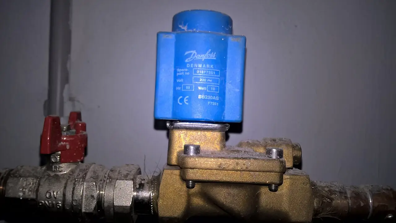
An angle seat valve is a 2/2 shutoff valve whose seat sits at an angle, typically 30 to 45 degrees, to the pipeline, closed by a stem that a pneumatic piston actuator drives along the flow axis, so the medium flows straight through the body in a lifted-seat, low-restriction path instead of turning through a tortuous chamber. The design pairs the isolation integrity of a seated valve with the cycle life of a pneumatic cylinder: catalog units commonly run 5 to 20 million cycles maintenance-free on steam, water, compressed air, and mildly aggressive duty, which is an order of magnitude beyond what a direct-acting solenoid valve survives at the same size in daily cycling service. The valve is the plant standard where a line must open and close thousands of times a day and must still hold bubble-tight against pressure when closed.
Specifying one is four linked decisions: the actuator architecture, single-acting spring return or double-acting, and its fail action; the seat and body materials against the temperature and chemistry window, PTFE to about 200 deg C on steam, PPL to about 250 deg C at reduced pressure, stainless steel bodies for corrosion and CIP duty; the capacity number, Kv at the real pressure drop, read against the straight-flow geometry that gives an angle seat roughly 30 to 50 percent more capacity than a same-size globe pattern; and the control accessories, pilot solenoid, stroke limiter, positioner, or limit switch box, that decide whether the assembly is a simple on-off machine or a throttling element. This page works each decision with catalog numbers and closes with the RFQ lines that make angle seat quotes comparable at engineering level.
This page treats the angle seat valve as a piston machine with a seat: actuator architecture and fail action, straight-flow Kv arithmetic, seat material windows for steam and chemistry, cycle life against steam conditioning cost, the boundary against solenoid, ball, diaphragm, and globe alternatives, and the RFQ lines that carry the whole specification.
Chapter 1 / 06
What an Angle Seat Valve Is and What Is Being Decided
The geometry defines the machine. The body presents an inlet and an outlet at an angle, with the seat ring set at 30 to 45 degrees to the pipe axis, and a disc-tipped stem moves into and out of that seat along the flow direction. Lift the stem and the medium passes under it in an almost straight line; the seat angle lets the flow sweep the seat area clean, which is why the pattern handles steam, saturated water, and lightly loaded liquids better than a right-angle globe body. Above the body sits the actuator: a pneumatic cylinder whose piston, sealed from the medium by a self-aligning stem packing, pulls the stem open against the line pressure and springs or air pressure closes it again. The assembly is compact because the cylinder and the valve share one axis, and it is durable because the only wear parts are the seat seal, the stem packing, and the cylinder seals.
What is being decided at purchase is rarely the geometry, which is standard, and always the operating architecture. First, the fail action: a normally closed valve holds shut on spring force and opens on air, the default for steam and water isolation; a normally open valve holds open on spring and closes on air, specified where the safe state is flow, boiler feed and cooling lines; a double-acting cylinder opens and closes on air with no spring, faster and more compact, for processes whose failure philosophy accepts last-position. Second, the medium window: pressure class, temperature, and chemistry together pick the body material, brass or stainless steel or hygienic bodies with polish and drain, and the seat seal, PTFE standard, PPL or metal-reinforced for hotter steam. Third, the capacity: Kv at the operating drop decides size, and the straight-flow body means an angle seat often runs one size smaller than the globe valve it replaces. Fourth, the control chain: an internal or attached pilot solenoid valve that consumes 1 to 4 watts to switch 6 bar of actuator air, a stroke limiter for soft seating, a position indicator or limit switch box for the PLC, and for throttling duty a positioner that turns the assembly into a bang-bang-free modulating element.
The competitive frame keeps the selection honest. Against the solenoid valve, the angle seat wins above roughly DN25 on steam and cycling water: the solenoid coil must force the whole pressure load directly, so size and heat rise cap it, while the pneumatic piston is air-amplified and runs cool; the solenoid wins below DN15 where simplicity, tight shutoff, and millisecond opening matter. Against the ball valve, the angle seat wins on speed and steam cycle life, a ball valve in daily steam cycling re-seats itself to death within a season where the angle seat runs millions of cycles; the ball valve wins on bidirectional tight shutoff at high differential and on manual economy. Against the diaphragm valve, the angle seat wins on pressure and temperature ceiling, the diaphragm wins on slurry and abrasive tolerance and on ultra-clean drainability in some geometries. Against the globe valve pressed into on-off duty, the angle seat wins on cycle count and price; the globe control valve with a valve positioner is the correct machine when the duty is modulation, not isolation. Each boundary is quantified in Chapter 3.
One positioning note: this page is the single-product page for the pneumatic piston angle seat machine. The solenoid valve family, the diaphragm valve, the ball valve, and the modulating control valve families each have their own pages; here the assumption is a cycled isolation duty on steam, water, air, or compatible process liquid, and every number that follows is chosen for that world.
Chapter 2 / 06
How the Piston Actuator and Angled Seat Work
The actuator is a single-acting or double-acting cylinder working against line pressure and spring force. In the normally closed architecture, springs sit inside the cylinder above the piston; vent the air and the springs drive the stem into the seat, holding against the differential until air at 5 to 8 bar, 6 bar the plant standard, lifts the piston and opens the valve. The force balance is the sizing arithmetic of the actuator: opening force equals air pressure times piston area, and it must exceed closing spring force plus the pressure load on the disc area plus stem friction; the catalog states a minimum and maximum supply pressure and a maximum differential pressure against which the valve still opens, and that differential line is a hard boundary, not a suggestion. A DN50 stainless angle seat at 6 bar supply typically holds 16 bar or more differential closed and opens against roughly 10 to 14 bar depending on seat design; oversized differentials need the next actuator size or double-acting operation.
The normally open architecture inverts the spring: the springs hold the valve open, and air pressure drives it closed. The pattern exists because steam and water lines fail air more often than they fail electricity, and the safe state on a boiler feed line is flow, not shutoff. The penalty is closing force: air must overcome spring force plus differential, so normally open units carry slightly lower differential ratings than their normally closed twins, and the RFQ should state the required closed-holding differential explicitly rather than accepting the catalog headline number. Double-acting cylinders drop the spring entirely: two air ports, open side and close side, driven by a 5/2 pilot valve; the assembly is smaller and faster, stroking in tens of milliseconds to a few hundred, but it holds no state on air loss unless the pilot solenoid is paired with trapped-pressure or reservoir logic, which the failure philosophy must then own.
The seat angle does the fluid work. A seat at 45 degrees to the axis presents a larger flow area for a given stroke than an across-the-line seat, so the valve reaches full Kv within a short lift, and the flow direction under the seat, media under the disc in the standard flow-to-open arrangement, sweeps the sealing zone and stiffens the stem against flutter. Flow over the seat exists as a specified alternative for long-life steam duty on some catalogs: it lets the medium pressure assist closing and keeps the seat out of the highest velocity zone, trading a few percent of Kv for seat life. The stem packing, typically PTFE chevrons self-aligning against the cylinder, seals the medium from the actuator for the whole life of the seals; on steam duty above 180 deg C the packing grade is a line item, because a standard PTFE set hardens and weeps while a high-temperature grade survives.
Actuator architecture
Fail position on air loss
Typical stroke time
Duty where it wins
Single-acting, normally closed
Closes on spring
0.3 to 2 s by size
Steam and water isolation, default
Single-acting, normally open
Opens on spring
0.3 to 2 s by size
Boiler feed, cooling, fail-flow lines
Double-acting cylinder
Last position or per pilot logic
0.05 to 0.5 s
High cycling, compact, fast duty
Double-acting with positioner
Last position
with 4 to 20 mA loop
Throttling as a low-cost modulator
The pilot stage is where electricity enters. An internal or yoke-mounted 2/2 or 3/2 solenoid valve switches the actuator air, consuming 1 to 4 watts at 24 V DC or 230 V AC, an order of magnitude less coil power than direct-acting the main valve would need, which is the second reason the architecture scales to DN100 and beyond where solenoid direct action stops. The pilot valve itself is a wear item with its own cycle life, commonly 10 to 30 million cycles for quality units, and on steam duty the pilot exhaust carries condensate, so the exhaust port silencer and drain belong on the installation drawing. A stroke limiter, an adjustable stop on some actuators, cushions the last millimeter of closing travel and measurably extends seat life on high-differential water duty by keeping water hammer out of the seat contact.
Cycle life arithmetic closes the chapter, because it is the number that justifies the machine. Catalog life for quality angle seat valves reads 5 to 20 million cycles, conditioned on medium, pressure, temperature, and lubrication: clean compressed air at moderate pressure carries the headline, saturated steam knocks it down several-fold, and dry running above 180 deg C halves it again unless the high-temperature seal kit is fitted. The plant arithmetic converts that to money: a valve cycled 60 times an hour, 8,000 hours a year, accumulates roughly half a million cycles a year, so a 10-million-cycle valve is a 20-year machine and a 1-million-cycle imposter is a 2-year machine with two decades of downtime installments. Ask the vendor for the life curve at the actual medium and temperature, not the brochure number at air.
Chapter 3 / 06
Bodies, Seats, and Duty Boundaries
Bodies divide by material and by end connection. Brass bodies, threaded BSP or NPT, serve compressed air, water, and neutral duty to about PN25 and 120 deg C media, the economy choice below DN40. Stainless steel bodies, CF8M-grade investment casting or barstock for smaller sizes, carry the pressure class to PN40 or PN63 and the corrosion window for steam, condensate, cleaning chemicals, and mildly aggressive process liquids; they thread, flange, weld, clamp, or use hygienic connections. Hygienic versions polish to Ra 0.8 um or better, self-drain by body geometry, and accept clamp or aseptic weld ends, serving food, beverage, and pharmaceutical CIP circuits where the valve sits in a cleanable line. Body size runs DN8 to DN100 as catalog standard, DN125 and DN150 as extended ranges from the major makers, with Kv climbing from about 1.9 cubic meters per hour at DN8 past 190 at DN100 in the straight-flow geometry.
Seat seals divide by temperature and by resilience. Standard PTFE seats serve minus 10 to plus 180 or 200 deg C and hold bubble-tight against the full body class at moderate steam pressure; they are the default and the cheapest. PPL, polyphenylene, seats extend steam duty to about 250 deg C at reduced pressure, the standard answer for low-pressure steam mains and hot oil-adjacent duty below its ceiling. Metal-seated or metal-laminate designs, stainless disc lapped to a metal seat with or without a graphite insert, push toward 300 deg C and beyond at the price of a leakage class one or two steps worse; they belong where temperature, not tightness, governs. Elastomer-backed seats, FKM or EPDM under a PTFE cap, buy resilience against particulate at modest temperature. The stem packing follows the same ladder in parallel, and the two materials must be specified together: a 250 deg C PPL seat behind an 180 deg C packing set is a leak scheduled for the second summer.
Seat and body combination
Temperature window
Typical pressure envelope
Hard boundary
PTFE seat, brass body, threaded
minus 10 to plus 180 deg C
PN25, Kv to about 40
Steam above 10 bar, chemistry
PTFE seat, stainless body
minus 10 to plus 200 deg C
PN40 to PN63 by size
Prolonged dry steam above 12 bar
PPL seat, stainless body
to plus 250 deg C
PN40 at reduced steam rating
Pressure falls as temperature rises
Metal or metal-laminate seat
to plus 300 deg C and beyond
by body class
Leakage class worse, cost higher
Hygienic body, PTFE or EPDM seat
CIP to plus 150 deg C
PN16 to PN25
Ra and drainability must be stated
Duty boundaries, sentence by sentence. High-cycling steam isolation, boiler lines, sterilizers, kettle feeds: the angle seat owns the duty, sized on steam Kv at the real drop with PPL or PTFE seats by temperature and a normally closed spring architecture. Cycling hot and cold water, washdown, CIP: stainless or hygienic bodies with EPDM or PTFE seats and normally open architecture where the fail state is flow. Compressed air piloting and distribution below PN16: the angle seat competes with the solenoid valve and wins on life above DN25, while the solenoid wins on cost and speed below. Abrasive and slurry-adjacent media: the diaphragm valve or a pinch valve owns the duty, the angle seat seats itself into early retirement. Sustained modulating control: the globe control valve with positioner owns the loop, the angle seat with positioner is a legitimate economizer on water-like media with modest rangeability demands, roughly 30 to 1. Tight bidirectional shutoff at high differential without cycling: the ball valve or needle valve wins. Large-diameter low-pressure air and water lines that cycle a few times a day: a butterfly valve driven by a pneumatic valve actuator or quarter-turn electric actuator is the volume answer, because the angle seat family stops near DN150. High-pressure steam mains above the catalog window: gate or globe isolation families, with the angle seat absent by rating.
The boundary that repeats every year is the steam sizing error. An engineer sizes a condensate or steam line on the water Kv, orders the valve, and the line runs starved because the catalog Kv for steam is stated at a reference drop and specific volume that the actual service does not reproduce. The correct method, worked in Chapter 4, converts the steam mass flow and operating pressures to an equivalent Kv before the size is fixed; on saturated steam the correction typically moves the selection one size, and on high-pressure steam with a large drop it moves it two.
Chapter 4 / 06
Key Specification Parameters
The decode table is the datasheet skeleton. Every row is an RFQ line, and the two right columns are what each row decides and what it costs to leave blank.
Parameter
Typical catalog spread
What it decides
Size and connections
DN8 to DN100, to DN150 extended
Line match, Kv ceiling, installation
Body material and class
brass PN25, stainless PN40 to PN63, hygienic PN16 to PN25
Corrosion window and pressure rating
Kv at operating drop
1.9 to about 190 cubic m per h by size
Real capacity, not the size label
Seat seal material
PTFE, PPL, metal-laminate, FKM or EPDM backed
Temperature ceiling and leak tightness
Actuator architecture and fail action
NC, NO spring, double-acting
Safety state on air and power loss
Supply pressure and differential limits
5 to 8 bar air, differential to about 16 bar by size
The Kv row is the one that separates engineering from quotation exchange. For liquids the calculation is direct: required Kv equals flow in cubic meters per hour divided by the square root of the drop in bar. For steam, the catalog method converts mass flow and operating pressure to an equivalent capacity using the specific volume at the actual upstream condition and a stated reference drop, and the number lands meaningfully below the water-derived figure; a DN25 valve carrying about 12 Kv on water is correctly a DN32 or DN40 selection on 8 bar saturated steam at 100 kilograms per hour. Fill the row with the actual operating pressures both sides of the valve, because sizing against supply pressure instead of line drop oversizes the valve and turns the seat into an orifice that never fully opens.
The differential row is the one that prevents the dead valve. Every actuator carries a maximum differential against which it will open, set by piston area, spring set, and disc area, and a normally open unit carries a lower closed-holding figure than its normally closed twin. The RFQ line is the worst-case differential, upstream minus downstream at maximum line condition, plus the statement that the valve must open against it at minimum declared supply pressure, 5 bar in plants with degraded air. A vendor answering only the body class has not answered the question; the body holds far more than the actuator can open, and the gap is where stranded inventory lives.
The accessories rows decide whether the assembly arrives complete. The limit switch box, mechanical or inductive, feeds open and closed states back to the PLC through an industrial relay or directly, and on steam duty it earns its price the first time a sticking pilot is caught in the alarm rather than in the cold kettle. The stroke limiter belongs on high-differential water duty as water hammer insurance. The positioner option, pneumatic or electro-pneumatic, converts the assembly for 4 to 20 mA or 0 to 10 volt throttling and is the bridge by which the angle seat competes for light modulating duty against a control valve at a third of the price, with rangeability roughly 30 to 1 and no characterized plug. The silencer and exhaust drain kit belong on every steam pilot, because pilot exhaust carries condensate and a blocked exhaust is a slow valve.
The certificate stack is the delivery ticket: PED 2014/68/EU conformity for pressure equipment jurisdiction, ISO 5211 or maker-standard mounting dimensions where accessories stack, ATEX or IECEx marking for the pilot coil in classified areas, ECCN-free declarations where export requires them, and material certificates EN 10204 3.1 for stainless bodies on audited projects. Hygienic service adds surface finish certificates and drainability statements against the cleanability audit. A quote missing the stack is not cheaper, it is later.
Chapter 5 / 06
Selection Decision Factors and RFQ Language
The decision sequence runs from the process outward, because every later step prices the earlier one.
Fix the fail action first, as a process hazard decision: normally closed for steam and general isolation, normally open where loss of air must not stop cooling or feed flow, double-acting only where the failure philosophy accepts last-position and the pilot logic is engineered for it.
Write the medium window: medium and its chemistry, minimum and maximum temperature, minimum and maximum pressure, and the worst-case differential at both temperature extremes, because steam ratings derate with temperature.
Compute required Kv at the real drop for liquid or converted steam duty, then choose the smallest size whose Kv at the operating point leaves 20 to 30 percent margin, using the straight-flow capacity rather than the nearest globe table.
Pick seat, packing, and body materials together against the window: PTFE standard, PPL for steam to 250 deg C, metal-laminate beyond, hygienic bodies and polish where the audit requires, and never a seat specified without its packing.
Check the actuator against the differential: minimum supply pressure and maximum differential must coexist in the vendor force table, or move one actuator size up before moving the valve size up.
Specify the control chain: pilot voltage and coil class, limit switch box type and contacts, stroke limiter where differential water duty demands, positioner where throttling is real, and the exhaust treatment on steam.
Close with the commercial lines: cycle life at the declared medium, seat and packing kit part numbers, delivery with certificates, and the price of one spare seal kit against the price of one unplanned stop.
The cost comparison is not the purchase price, it is the seal-kit economics. A quality stainless angle seat at DN50 prices two to three times a brass-bodied commodity unit, and the commodity unit prices attractively until its seat kit is fitted twice a year against a five-year interval, at line downtime rates the first invoice already exceeded. Table the decision on cost per cycle: purchase price plus expected seal kits over the declared life divided by the cycle count at the actual medium. On that arithmetic the 10-million-cycle valve at twice the price is a third of the cost, and the steam-duty PPL seat at 15 percent premium pays at the first avoided seasonal replacement. The valve that wins the tender on price and loses the plant on cycles is a documentable failure, which is why the cycle-life line with medium conditions belongs in the RFQ rather than in the vendor brochure.
Duty
Architecture and materials to specify
Watch line
Steam isolation, cycling
NC stainless, PPL or PTFE by temperature, silencer and drain
steam Kv conversion, derating curve
Hot water, CIP, washdown
NO or NC stainless, EPDM or PTFE, limit box
fail state, water hammer limiter
Compressed air distribution
NC brass or stainless below PN16, high cycling
crossover vs solenoid valve at DN25
Light throttling on water-like media
Double-acting with positioner, 4 to 20 mA
rangeability about 30 to 1
Hygienic CIP line
Hygienic body, polish Ra 0.8 um, clamp ends
drainability and certificates
The RFQ language that makes quotes comparable, written as the datasheet lines a vendor must answer with numbers: size and Kv at declared drop; body material and pressure class; seat and packing materials with temperature limits at the declared medium; actuator architecture with fail action; minimum supply pressure at which the maximum declared differential is held and opened; pilot voltage, power, and duty rating; stroke time at 6 bar; cycle life at the declared medium and temperature, with the seal kit part number and interval; accessories delivered fitted; certificates supplied. A quotation answering those lines is a specification; anything else is a price attached to a hope.
Chapter 6 / 06
Installation, Standards, Failure Modes, and Maintenance
Installation follows the flow arrow and the drain plan. The standard flow-to-open arrangement installs with the medium entering under the seat, and the body arrow decides orientation; installing against it costs capacity and seat life and voids the differential table. The actuator may install upright or horizontal on most catalogs, but upright keeps condensate out of the cylinder on steam duty and is the default drawing. Provide a manual override or a bypass around any single valve whose failure stops the process, because a spring machine that has failed closed with the line full is a locked line until the pressure is relieved. Give the pilot exhaust a silencer and, on steam, a drain path; pilot exhaust water is the most common false diagnosis of a failed valve, and the second most common is a supply regulator set below the minimum opening pressure.
The standards frame is straightforward and mostly about evidence. Sizing and leakage language aligns with EN 12266-1, leak rate A bubble-tight against the declared differential, and the vendor test certificate against that standard is a line item worth demanding on audited projects. Pressure equipment falls under PED 2014/68/EU in the European jurisdiction with the category assessment by volume and class; the pilot coil in classified areas carries ATEX or IECEx marking for its group and temperature class; hygienic units answer cleanability with surface finish and drainability documentation against the plant audit rather than a single seal. Electromagnetic compatibility for the pilot is CE and, where the control chain requires, listed to the plant's low-voltage directives. None of these are exotic; the failure mode is buying a valve whose file arrives without them and discovering it at commissioning.
Failure modes arrive in a predictable order, and each has a specification answer. Seat wear shows as weeping at closed position after some millions of cycles or one season of dry steam: the answer is the correct seat material for temperature, a stroke limiter on water hammer duty, and the seal kit scheduled at the cycle-life interval rather than at the leak. Stem packing wear shows as external weep at the actuator joint on hot duty: the answer is the high-temperature packing grade specified with the seat and replaced together with it. Pilot sticking shows as slow or half travel: the answer is a clean, dry air supply with a filter regulator at the valve and exhaust silencers that do not blind. Cylinder seal wear shows as the valve failing to open at what used to be adequate supply pressure: the answer is minimum supply pressure margin in the sizing and a seal kit in the stores. Water hammer damage shows as seat hammering and body stress on long water lines: the answer is architecture, normally open or double-acting with timed piloting, a stroke limiter, and line velocity discipline, not a stronger seat.
Maintenance is a seal-kit economy by design. The wear parts, seat, stem packing, cylinder seals, and pilot service kit, are field-replaceable on every quality catalog without removing the body from the line on threaded and clamped units, and the interval is the declared cycle life at the actual medium, discounted by half for sustained steam at the top of the temperature window. Keep one full kit per valve size in stores for the fleet, not one per valve, and log the cycle count against the kit interval the way rotating equipment logs hours. The annual check is five minutes: stroke the valve against the differential, watch the travel time against the commissioning record, verify the limit box indication, and feel the pilot exhaust. A valve that opens slower than commissioning is telling the maintenance planner its future; listening at year one converts a failure into a kit change.
The commissioning record closes the loop and is the cheapest document on the page. Record supply pressure at the valve under flow, stroke time both directions, differential at test, pilot voltage and current, and the seal-kit lot numbers fitted. That record, one page per valve, is the baseline for every later slow-travel diagnosis and the evidence base for the cycle-life warranty conversation. Plants that keep it replace seats on schedule; plants that do not replace valves on emergency.
FAQ
When does an angle seat valve beat a solenoid valve?
Above roughly DN25 on cycling duty, the angle seat wins: the pneumatic piston is air-amplified so it stays compact and cool while a direct-acting solenoid coil must force the whole differential electrically, capping size and life. Below DN15 with infrequent cycling and tight shutoff, the solenoid valve wins on simplicity and millisecond speed. On steam, the crossover moves smaller, because coil heat and condensate shorten solenoid life faster than piston wear.
Normally open or normally closed, how do I choose?
Choose the fail state as a process hazard decision. Normally closed, spring holds shut, is the default for steam and general isolation because air or power loss should stop flow. Normally open, spring holds open, belongs on boiler feed, cooling, and any line where loss of flow is the dangerous outcome. Double-acting drops the spring for speed and compactness and accepts last-position on air loss, so the pilot logic must be engineered for that.
How hot and how high pressure can an angle seat valve go?
PTFE seats serve to about 180 or 200 deg C and PN40 to PN63 in stainless bodies; PPL seats extend steam duty to about 250 deg C at reduced pressure ratings; metal-laminate seats reach around 300 deg C with a worse leakage class. The stem packing must match the seat grade, and steam pressure ratings derate with temperature, so the RFQ should state the pressure required at the top of the temperature window, not the catalog headline.
What cycle life should I expect?
Quality catalogs declare 5 to 20 million cycles, conditioned on medium: clean air carries the headline, saturated steam cuts it several-fold, and top-of-window temperatures halve it again without high-temperature seals. A valve cycled 60 times hourly for 8,000 hours a year accumulates about half a million cycles, so the declared figure is a decade-scale number. Demand the life curve at your actual medium and temperature, and schedule the seal kit at that interval.
How do I protect the valve and line against water hammer?
Water hammer is an architecture problem before a valve problem. Specify normally open or double-acting operation with timed piloting on long water lines, fit the stroke limiter so the seat does not slam the last millimeter, and keep line velocities within design discipline. On pumping circuits, the centrifugal pump ramp behavior and check valve selection on the discharge belong in the same review, because hammer generated at the pump arrives at the seat regardless of the valve.
Can an angle seat valve be used for modulating control?
Yes, as an economical light-duty modulator. Fitted with a positioner, the double-acting assembly accepts 4 to 20 mA and throttles water-like media with rangeability around 30 to 1, competing with a globe control valve at a third of the price. For characterized control, high rangeability, steam pressure reduction, or noise-critical service, the control valve with its valve positioner remains the correct machine; the angle seat economizes only within its envelope.
What maintenance does the valve need?
A seal-kit economy: seat, stem packing, cylinder seals, and pilot service kit are field-replaceable without removing the body on threaded and clamped units. Schedule the kit at the declared cycle life at your medium, halved for sustained steam at the top of the window, and keep one kit per valve size in stores. The annual five-minute check is stroke time against the commissioning record, limit box indication, supply pressure under flow, and pilot exhaust condition; a slowing stroke is the kit's appointment being made.