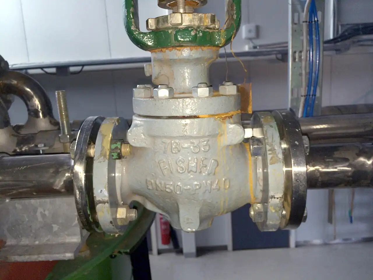
A globe control valve is the process industry's modulating workhorse: a globe-bodied valve whose plug moves axially against a seat ring, changing the flow area continuously between closed and full travel, driven by an actuator that follows a controller signal. Sizing and construction follow the IEC 60534 standard family, with capacity expressed as Kv or Cv, the flow that passes at a stated pressure drop, and the valve's job is not isolation but regulation: holding flow, pressure, level, or temperature at a setpoint by continuously trading pressure drop for flow. Where an isolation globe valve is designed to sit open or closed, the control version is designed to live at part travel, thousands of hours a year, with a trim that keeps its characteristic stable while it does.
Specifying one is five linked calculations and one architecture choice: size the capacity at multiple operating cases, not one; choose the flow characteristic so the installed gain stays uniform; check the pressure-drop physics for choking, cavitation, and noise; select the trim and materials that survive that physics; and pair the actuator, positioner, and fail action so the valve actually moves as commanded when the plant air is at its worst. This page works each of those with catalog numbers, draws the boundary against ball, butterfly, and rotary alternatives, and closes with the RFQ lines that make control valve quotes comparable at engineering level.
This page treats the globe control valve as a computing element made of metal: IEC 60534 sizing across the real operating envelope, inherent versus installed characteristic, cavitation and noise physics with the trims that manage them, leakage class arithmetic, actuator and positioner pairing, and the process datasheet lines an RFQ must carry.
Chapter 1 / 06
What a Globe Control Valve Is and What Is Being Decided
The globe body puts two ports in line with a seat between them and a plug that moves toward and away from the seat, and that geometry is why the design controls well: the flow path changes area smoothly with travel, the plug can be contoured to shape the gain, and the pressure drop is taken across a short, controlled restriction rather than around a rotating ball or disc. The control valve built on that body adds the hardware that turns geometry into regulation: a bonnet and packing that seal the moving stem, a yoke carrying an actuator, pneumatic diaphragm or piston, electric, or hydraulic, and a positioner that compares commanded signal with stem position and drives the actuator until they agree. The valve is a loop element: its input is 4 to 20 mA or a digital signal from the PLC or DCS, its output is a flow that the process then measures, with a pressure transmitter or its siblings feeding the controller that closes the loop.
What is being decided is not whether a globe shape works, it is what the valve must compute and survive. First, capacity: the required Cv or Kv at the maximum and minimum operating cases, because a valve sized on one flow point will either breathe at the bottom of its travel or saturate at the top. Second, characteristic: linear or equal percentage, chosen so that the valve-plus-pipe-plus-pump system gain stays flat as the valve travels, which is the difference between a loop that tunes once and a loop that retunes every season. Third, pressure-drop physics: whether the service chokes, cavitates, flashes, or generates aerodynamic noise beyond limits, and the trim and staging that prevent those. Fourth, shutoff: the leakage class the process needs at full closed, a specification that changes the trim and the actuator force budget. Fifth, the actuation architecture: pneumatic, electric, or hydraulic, spring fail action, and positioner protocol. Each decision prices the next, and the RFQ exists to carry all five with numbers.
The competitive frame keeps the selection honest. Against a rotary control valve, a segmented ball or high-performance butterfly pattern: the globe owns precise repeatable control at small and mid sizes and the highest pressure drops per size; the rotary owns large diameters and price at moderate duty, which is why DN400 cooling water uses butterfly bodies and DN50 steam trim uses globe. Against a plain ball valve or butterfly valve pressed into modulation by a positioner: those are isolation geometries, their characteristics are poor near closed, and their seats wear out in a season of real throttling. Against on-off alternatives such as a knife gate valve or check valve, there is no contest because there is no common duty. And where the process question is how fast to run a motor rather than how much flow to pass, the answer is a VFD on the pump, not a valve burning the head as noise and wear, an honest trade the selection review should make explicitly before the valve RFQ goes out.
One positioning note: this page is the single-product page for the modulating globe machine. The generic control valve family landscape and the isolation-weighted globe valve page sit beside it; here the assumption is a modulating duty with a controller in the loop, and every number that follows is chosen for that world.
Chapter 2 / 06
Sizing, Characteristic, and Pressure-Drop Physics
Capacity arithmetic to IEC 60534-2-1, the ISA-75.01 equivalent, expresses what a valve passes in one number: Kv, cubic meters per hour of water at one bar of drop, or Cv in imperial units, and the equations convert process conditions, flow, upstream pressure, drop, temperature, density for liquid, or specific gravity and compressibility for gas, into a required Kv at each case. The sizing discipline is the cases: normal, maximum, and minimum flow with their real upstream and downstream pressures, because the pressure drop across a valve in service is set by the system curve and the pump, not by the datasheet's imagination. A valve is correctly sized when maximum flow lands near 80 to 90 percent of travel and minimum flow sits above 10 to 20 percent, inside the rangeability the trim can hold, commonly 50 to 1 for quality globe trims, higher for special cages. Oversized valves, the industry's default disease, spend their lives below 20 percent travel where the characteristic is steep, the stem cuts the seat, and the loop hunts.
The characteristic is the gain curve. Inherent characteristics, linear, equal percentage, quick opening, describe flow fraction versus travel at constant drop; equal percentage, by far the most specified, increases flow by a fixed ratio per unit travel, giving the valve low gain near closed where the system needs gentleness. Installed characteristic is what the process sees once the pump and pipe share the drop: as travel opens, the valve takes less of the system drop and the installed curve flattens toward linear. The selection rule follows: systems where most of the drop stays across the valve at all flows want linear; pump systems where the valve's share of drop shrinks at high flow want equal percentage, because its exponential inherent curve cancels the system's flattening. State the choice in the RFQ with the reasoning case, because it is the row that decides loop quality for the next decade.
Pressure-drop physics decides valve survival. Liquids: when the pressure at the vena contracta falls below the vapor pressure, vapor forms; if the pressure recovers above vapor pressure downstream, the bubbles collapse as cavitation, which sounds like gravel and removes trim metal in weeks. The sizing equations flag the choked drop, and the fixes are staged, pressure-drop-splitting trims, multi-hole cages, and two valves in series, before the service is accepted. If the downstream stays below vapor pressure, the vapor survives as flashing: no cavitation noise, but hard erosion of the trim and outlet, answered by angle bodies and hardened materials rather than by staging. Gases and steam: the physics is aerodynamic noise, jet power at the vena contracta, predicted by IEC 60534-8-3, and the specification states the limit, commonly 85 dBA at one meter or a plant-specific number, with low-noise trims, drilled-hole cages and multi-stage paths, as the engineered answer. These are computable quantities, and a control valve RFQ without a noise calculation for gas service is a complaint generator on a delivery pallet.
Shutoff arithmetic closes the chapter. Leakage class to IEC 60534-4 and FCI 70-2 scales from Class II through Class VI: Class IV, 0.01 percent of rated capacity, is the standard metal-seat class for modulating service; Class V serves higher-seal duties with tighter numbers per drop; Class VI is soft-seat bubble-tight and belongs where the valve must actually isolate. Class choice moves the actuator force budget, because higher shutoff at higher drop means more seating force, and it moves the trim materials, because tight shutoff across a hard drop concentrates wear exactly where the plug meets the seat. Specify the class with the differential at which it must hold, not the class letter alone.
The speed of response is the last quantified behavior: stroking time full-to-full, seconds for most globe assemblies with pneumatic actuators, faster with volume boosters, and the loop's tuning assumes it. Where the process needs both tight modulation and fast fails, the architecture pays for both, and Chapter 5's accessory list is where those parts get named so they arrive as one tested assembly rather than an integration project.
Chapter 3 / 06
Trims, Bodies, and Duty Boundaries
Trim divides by guidance and by staging. Single-seat unbalanced trims, one contoured plug in a seat ring, guided by the seat and the stem: simple, tight, and force-limited, because the whole upstream pressure acts on the plug, so unbalanced designs serve moderate drops and sizes. Balanced plugs carry a seal to the plug's backside, a cage hole or balancing ring, canceling most static force so one actuator can hold a far higher drop shut: the standard process trim of the family. Cage-guided trims put the plug inside a drilled or contoured cage that guides it over full travel and shapes the characteristic with the cage windows, and the cage is where staging lives, multi-step and multi-hole cages that split the drop into many small recoveries to keep the vena contracta above vapor pressure, the anti-cavitation pattern, and labyrinth and drilled-path cages that cut jet power for low-noise gas service. Top-guided and post-guided trims close the list for smaller duties, and the balanced cage pattern is what the phrase process control trim means in most catalogs.
Bodies divide by service path. Straight-pattern globe, the default two-way modulator; angle pattern for flashing and erosive service and bottom-outlet duties; three-way bodies for mixing and diverting where one valve replaces two; small forged bodies for high pressure and instrumentation-adjacent duty; and barstock bodies for cryogenic and high-alloy economies. Bonnets divide by temperature and sealing: plain bolted bonnets for ambient service, extended bonnets to move packing away from cryogenic and high-temperature extremes, bellows-sealed bonnets where emission limits or lethal service demand stem sealing beyond packing, and packing sets themselves ladder from PTFE through graphite to live-loaded graphite arrangements qualified to the fugitive-emission standards. Materials follow the pressure vessel ladder: WCB carbon steel baseline, WC6 and WC9 chrome-moly for steam temperatures, CF8M and CF3M stainless for corrosion service, duplex and higher alloys by chemistry, with trim hardfacing, chrome plating, and cobalt or nickel overlays wherever drop and erosion concentrate.
Trim or body pattern
Duty class
Typical envelope
Hard boundary
Unbalanced single seat
Simple, tight shutoff
small size, moderate drop
Actuator force ceiling on high drop
Balanced cage trim
General process modulation
DN15 to DN500, class 150 to 900
Balancing seal is a wear item
Multi-stage anti-cavitation
High-drop liquid
by staged drop, tens of bar
Price; solids tolerance
Low-noise cage, gas
Steam and gas pressure reduction
to 85 dBA and below at 1 m
Capacity per size is lower
Angle body, hardened
Flashing and slurry-adjacent
high delta P erosive duty
Not for tight mixed service
Bellows bonnet
Emission-critical, lethal
by pressure class
Cost; cycle-life of bellows
Duty boundaries, sentence by sentence. Small to mid size, high drop, precise control: the globe owns it. Large diameter, moderate drop, price pressure: butterfly bodies and segmented ball patterns take over, control valve families with their own trim engineering. Extreme staging, tens of bar drop on liquid or steam: multi-stage globe trims and multi-valve trains, sized by the calculation, not the brochure. High temperature steam above the chrome-moly window and hydrogen service: welded and special construction with the maker's letter, not catalog optimism. Cryogenic: extended bonnet, the right trim clearances, and the cryogenic test report in the certificate stack. Sanitary and high-purity: the globe family recedes and specialized aseptic valves own the duty. And the boundary that repeats every year: if the duty is really start-stop or divert with a little trim, buy the isolation valve that truthfully serves it and the control element separately, or the plant buys both again in three years.
Chapter 4 / 06
Key Specification Parameters
The decode table is the datasheet skeleton. Every row is an RFQ line, and the two right columns are what each row decides and what it costs to leave blank.
Parameter
Typical catalog spread
What it decides
Size and class
DN15 to DN500, class 150 to 2500 by pattern
Envelope, nozzle match, rating basis
Rated Cv or Kv, and required Kv at cases
per size and trim, 3 cases minimum
Travel utilization and rangeability honesty
Flow characteristic
linear, equal percentage, quick open
Installed gain flatness and loop quality
Leakage class at differential
Class IV standard, V, VI by seat
Shutoff truth and actuator force budget
Max shutoff differential
by trim balance, to class delta
Actuator sizing at worst case
Noise prediction
IEC 60534-8-3, 85 dBA at 1 m typical limit
Trim staging and silencer scope
Body, trim, and facing materials
WCB, WC6, WC9, CF8M, duplex, hardfacing
Temperature, chemistry, erosion life
Actuator and fail action
pneumatic diaphragm or piston, electric, hydraulic
Stroking speed, failure position, air supply fit
Positioner and signal
4 to 20 mA, HART, fieldbus, digital
Loop integration and diagnostics
Temperature range and bonnet
minus 196 to plus 600 deg C by construction
Packing and lubrication survival
Emission and certificates
ISO 15848 or API 624, NACE, PED
Legal install and fugitive compliance
The required-Kv row is the one that separates engineering from quotation exchange. A vendor's rated Cv says what the valve could pass wide open; the buyer's required Cv at the maximum case with real pressures says whether the valve is a servant or a bottleneck. Fill the row with three cases, and the chosen trim is judged by travel utilization, and rangeability becomes a number in use rather than a catalog adjective.
The noise row belongs on every gas and steam service, not only the loud ones, because the calculation is cheap and the retrofit is not. State the limit, the prediction standard, and the observation distance with the calculation attached to the quote; low-noise trim priced at purchase is a fraction of the silencer and rework priced after startup. The cavitation statement belongs on every high-drop liquid service in the same spirit: the check, either choked or not, either damaging or not, with the staged trim that follows when it is.
The actuation rows decide whether the assembly is a valve or a machine. Air supply pressure at the worst winter case sizes the pneumatic valve actuator; the fail action, spring-to-close, spring-to-open, double-acting with trapped pressure, is a safety architecture decision the process hazard analysis owns; the positioner protocol is the loop integration line, 4 to 20 with HART as the plant default, fieldbus where the control system speaks it natively. The electric actuator alternative prices higher and carries its own failure philosophy; the hydraulic valve actuator serves the highest force and speed duties; and a scotch yoke actuator, the quarter-turn pattern, belongs to the rotary valve families this page competes with, not to the globe. Name the accessory list in the same order: positioner, solenoid, limit switches, air filter regulator, volume booster where speed demands, so the tested assembly is complete.
The certificate stack is the delivery ticket: performance to IEC 60534, fugitive emission to ISO 15848-1 or API 624, sour service to NACE MR0175 or ISO 15156 where flagged, PED 2014/68/EU conformity by jurisdiction, fire-safe type testing where hydrocarbon service invokes it, and material certificates per EN 10204 by project class. A quote missing the stack is not cheaper, it is later.
Chapter 5 / 06
Selection Decision Factors and RFQ Language
The sequence runs from process truth to assembly, and each step is a calculation someone signs.
Write the process datasheet: fluid, flow at normal, maximum, and minimum cases, upstream and downstream pressures per case, temperatures, density and vapor pressure for liquids, compressibility for gas, and the pipe schedule the valve joins.
Compute required Kv per case to IEC 60534-2-1, check choked flow, cavitation, and flashing flags, and select size and trim so travel utilization lands 10 to 90 percent across the envelope.
Choose characteristic from the system curve, equal percentage for pump systems whose valve drop share falls with flow, linear where the drop share is constant.
Run the noise prediction for gas and steam to IEC 60534-8-3 against the stated limit, and select low-noise staging where the number exceeds it.
Set the leakage class and the shutoff differential, then size the actuator at worst-case supply and differential with the fail action the hazard review chose.
Set materials by chemistry and temperature, bonnet and packing by emission class, and the certificate stack by jurisdiction and service flags.
Write the RFQ with the datasheet, the three-case Kv table, the noise limit, the class and differential, the fail action, and the accessory list, and evaluate quotes row against row.
Cost behavior follows size, staging, and actuation. As a planning spread on the same duty: a small pneumatic globe assembly, DN25 class 150 with diaphragm actuator and positioner, sits at the family baseline; each pressure class step adds 20 to 50 percent; multi-stage and low-noise trims add 50 to 200 percent by staging depth; bellows bonnets and alloys add material-driven steps; electric actuation prices 1.5 to 3 times pneumatic at equal duty; and at large diameters the rotary takeover arrives, a high-performance butterfly or segmented-ball control assembly commonly undercutting the globe by half at DN300 and above. Against the electronics alternative, a VFD trimming a pump compares in total cost of energy: where the system can vary speed instead of burning head, the drive wins the operating cost argument outright, and the valve wins where precise hydraulic staging or rapid fail isolation is non-negotiable.
Option pair
Relative cost, same duty
What you gain
What you pay in
Standard cage vs multi-stage trim
1.0 vs 1.5 to 3
Cavitation and noise survival
Price, capacity per size
Pneumatic vs electric actuation
1.0 vs 1.5 to 3
No air supply, positioning precision
Cost, failure philosophy, speed
Globe vs rotary at DN300 and above
1.0 vs 0.5 to 0.8
Price and weight at large size
Control precision, high drop behavior
Metal Class IV vs soft Class VI seat
1.0 vs 1.1 to 1.3
Bubble-tight shutoff
Temperature and cycle ceiling
Control valve vs VFD on the pump
1.0 vs 2 to 4 capital
Energy: speed instead of head burn
Where staging or fail isolation is required
The RFQ package is the two datasheets plus the numbers: process datasheet with all cases; mechanical datasheet with size, class, ends, materials, bonnet, packing, and certificates; the three-case Kv table; the characteristic with reasoning; leakage class at stated differential; noise limit and prediction basis; actuator type with supply conditions and fail action; positioner protocol; accessory list by name; and the acceptance tests, seat leakage, stroke, and stroking time, with witness points. Quotes that answer all rows are comparable to each other and to the engineering; quotes that skip rows are cheaper in the way the missing rows explain.
The surrounding system completes the review: block and bypass, isolation by a full-bore ball valve or a tight gate valve each side with a bypass globe valve for manual trim, a strainer where construction debris is real, a check valve where reverse flow can unload the trim, and the loop instruments, the pressure transmitter or flow element whose signal the controller acts on. The soft starter on the motor next door and the PLC cabinet are loop citizens too: the valve that arrives with its positioner speaking the plant protocol is the valve that starts up in a day rather than a month.
Chapter 6 / 06
Installation, Standards, Failure Modes, and Maintenance
Installation is loop commissioning, not just piping. Flow direction matters: most globe trims are stamped flow-to-open or flow-to-close, and the choice trades seating force against stem stability, so the stamp and the piping agree. Give the valve the straight runs it assumes, a few diameters upstream and downstream where space allows, because elbows at the port disturb the capacity the sizing assumed. Support the assembly for its mass with actuator full, keep the positioner and its tubing accessible, and run the air supply through the filter regulator that came with the accessory list, because instrument air grit is a positioner's shortest career. Before first stroke, confirm the fail action by cutting air with the loop watching: the valve that fails the wrong way is a finding, and startup is the cheap time to find it.
Commissioning numbers go on the record: full-open and full-closed travel against the positioner calibration, stroking time both ways, seat leakage at test differential where the system allows, and the loop tuning constants that followed. Every future condition judgment, hunting, slow response, seat wear, reads against this baseline, and the file costs an hour at startup and saves every year after.
The standards frame is the family's backbone: IEC 60534 sizes capacity, characteristic, and noise, Part 2-1 for flow equations, Part 8-3 for aerodynamic noise, Part 4 for leakage classification; ISA-75 mirrors it in the American corpus, ISA-75.01 sizing at its center; ASME B16.34 rates the body, B16.5 and B16.10 the flanges and face-to-face; ISO 15848-1 and API 624 qualify fugitive emissions; NACE MR0175 and ISO 15156 govern sour materials; PED 2014/68/EU covers the European pressure regime. A control valve is one of the few plant components whose behavior is standardized this completely, and an RFQ that cites the paragraphs gets answers built to them.
Failure modes rank by plant experience. Cavitation damage first on mis-sized high-drop liquids: gravel noise, then a chewed plug and cage, and the cure is the staging the sizing review skipped, plus trim hardfacing as palliative. Packing leakage second, presenting as weep or fugitive finding, cured by live-loading, the right set for the temperature, and re-torque to table values; bellows upgrades where the service demands zero. Positioner and actuator problems third, hunting from poor tuning or worn positioner, sluggish response from supply starvation, and the diagnosis is the baseline stroking-time comparison. Seat and plug wear fourth, the slow capacity loss and characteristic shift at the bottom of travel that oversized valves punish themselves with, found by the travel histogram the smart positioner keeps. Flashing erosion and corrosion close the list on the chemistries that earned them, answered by angle bodies, hardened trim, and the material ladder at selection. Nearly every entry traces to a sizing or specification decision made before the valve existed, which is the quiet argument for doing Chapters 2 and 5 in writing.
Maintenance is condition-based against the baseline: travel histogram and stroke time from the positioner's diagnostics on smart assemblies, packing adjustment at intervals the emission class sets, trim inspection at turnarounds with plug, seat, and cage measured against wear limits, and the soft goods, seat seals, packing, gaskets, replaced on every internal opening as policy. The balancing seal on balanced plugs is a wearing part with a service life; carry it as a spare. And the loop retunes after any trim change, because a new trim is a new gain curve, and the controller still believes the old one until someone tells it otherwise.
FAQ
Why does the datasheet want three flows instead of one?
Because a control valve lives at part travel and its quality is judged across the envelope. Size on the maximum case alone and the valve breathes near closed at normal flow, cutting the seat and hunting the loop. Required Cv at normal, maximum, and minimum with real pressures puts travel utilization between roughly 10 and 90 percent, which is the whole sizing discipline.
Linear or equal percentage characteristic, which do I order?
Follow the system curve. If the valve takes a roughly constant share of system drop across flows, linear keeps gain flat. In pump systems where the valve's drop share collapses as flow rises, equal percentage cancels that collapse and keeps the loop uniform, which is why it is the default in process plants.
What is cavitation and how do I specify against it?
Liquid pressure at the trim's vena contracta falls below vapor pressure, forms vapor, then collapses downstream as cavitation, attacking trim metal audibly and quickly. The IEC 60534 sizing flags it. Specify multi-stage or multi-hole trims that split the drop, or two valves in series, and hardfaced materials as the support act, not the cure.
How is valve noise limited on steam and gas service?
Aerodynamic noise is jet power at the vena contracta, predicted by IEC 60534-8-3. State the limit, commonly 85 dBA at one meter, in the RFQ and require the calculation with the quote. Drilled-path and labyrinth low-noise cages cut jet power at the source, far cheaper than silencers or rework after startup.
What leakage class does a modulating valve need?
Class IV, 0.01 percent of rated capacity, is the standard metal-seat class for regulation duty. Choose Class V or VI only when the closed valve must genuinely hold, and state the differential at which it must hold it, because the class letter alone sizes neither the seat nor the actuator force.
Pneumatic or electric actuation for a new plant?
Pneumatic with spring fail action remains the process default: fast, force-dense, and fails predictably without power. Electric suits isolated duties without instrument air and precision positioning at moderate speed. Choose the fail position first, as a hazard-review decision, then the actuator that delivers it at worst-case supply.
When is a VFD on the pump the better control than this valve?
When the system can trade speed for flow and recover the energy a valve would burn as drop and noise, the drive wins on operating cost across most load profiles. The valve wins where hydraulic staging, rapid fail isolation, or pressure regulation independent of a pump is required. Make the trade explicitly in the selection review, not by habit.