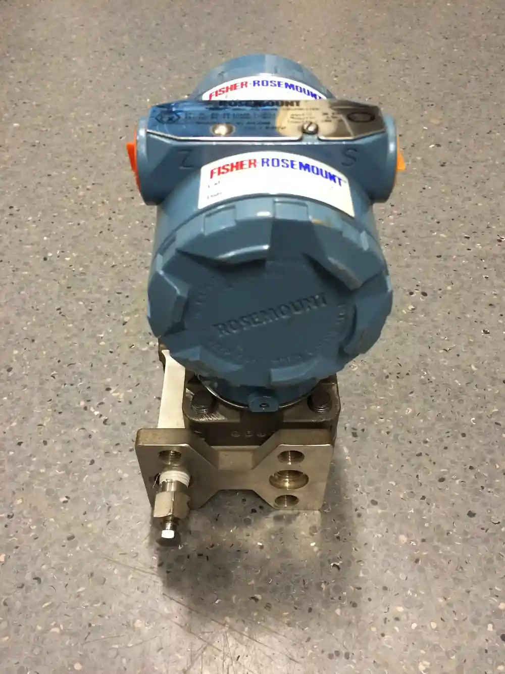
A differential pressure gauge is a self powered mechanical instrument that indicates the difference between two pressures, through two process ports marked high and low, with no external energy of any kind. Both sides of the instrument carry the full line pressure at all times while the movement responds only to the difference between them, and that double duty is what separates this instrument from an ordinary pressure gauge and drives its most important specification row, the working static pressure limit. Sensing elements divide into three families: the magnetic piston, an unbalanced piston sealed by an O-ring whose magnet drives a dial flag through the wall; the diaphragm capsule, an elastomer, PTFE, or metal diaphragm between two chambers, capable of spans from 0 to 25 mbar; and opposing bellows or dual Bourdon elements, differentially coupled, with reed switches for alarms. Spans run from tens of millibar to tens of bar, with working static ratings typically in the 100 to 400 bar class and accuracy classes of 1.6 to 2.5 percent of span common.
Procurement engineers meet these gauges at filter and strainer stations, where the reading across a Y strainer or basket strainer element says when to clean or swap it; at pump suction and discharge and fan inlets, where the differential is the health number; across clean rooms and isolation wards, where rooms are held at a few tens of pascals relative to corridor; and at primary flow elements, where the gauge gives a local flow indication where a powered loop is not justified. The decision this page settles is narrow and practical: which element family fits the span and the media, what static pressure limit the line can actually impose, what wetted materials and options, contacts, liquid fill, square root dial, manifold, belong on the order. The answer lands as an RFQ line set, and every chapter below feeds that line set so the gauge reads true for years without a power supply.
This page treats the differential pressure gauge as a purchasing object: what piston, diaphragm, and bellows elements each do to the span and the static pressure limit, how filter monitoring and clean room duty set the range, what EN 837-1 and ASME B40.100 demand of the instrument, and how span, static limit, wetted materials, fill, and contact options combine into a defensible RFQ. It is written for engineers who specify local indication for procurement packages, not for readers who want a catalog tour.
Chapter 1 / 06
What a Differential Pressure Gauge Is and What Is Being Decided
The instrument is defined by what it subtracts. An ordinary pressure gauge reads one process pressure against atmosphere through a single port; a differential pressure gauge reads two process pressures against each other through two ports, and its pointer rests at zero when both sides are equal no matter how high the common pressure stands. That subtraction is performed mechanically, by an element that sees the difference of two forces rather than one, and the entire engineering of the instrument is in letting the element move accurately while the case, the movements, and the seals hold static pressure that can be a thousand times the measured span. A gauge reading 0 to 25 mbar across a filter on a 100 bar line is holding four thousand times its full scale on both sides, and that number, the static pressure limit, is the line that decides whether an instrument survives commissioning.
What is being decided at purchase is a set of rows that interact. The span, chosen against the differential the process actually produces, dirty filter alarm point or fan curve or room class, so the needle works in the middle of the dial rather than the first tenth. The static pressure limit, chosen against the worst pressure the connected side can see, including pump shutoff and closed valve conditions, not the normal operating pressure. The element family, chosen against span, media, and overrange likelihood. The wetted materials, chosen against chemistry; 316L for chemically clean duty, copper alloy for economy on benign service, elastomer or PTFE diaphragms where they form the barrier. And the option set: reed switch alarm contacts, liquid fill for pulsation, a square root dial when the gauge reads a flow element, and a manifold to make zero checks possible.
The instrument's classic habitat is filtration and straining. Across a Y strainer element the differential climbs from a clean baseline near zero as the screen loads, and practice sets the alarm or changeover point near 0.5 to 1.0 bar of dirty delta or per the element's pressure drop curve at design flow; the gauge turns that curve into a daily walk past the skid. Across a basket strainer the same reading schedules basket cleaning before the element lifts or collapses. On a duplex strainer the gauge justifies the changeover: operators switch banks on evidence, not on calendar, and the differential is reset to near zero by the clean side. The same arithmetic serves cartridge filter banks, air handling units, and heat exchanger fouling trends, which is why the dp gauge, or differential pressure indicator as older plant documents call it, is one of the highest count instruments on a fluid skid.
The boundary against the electronic sibling should be stated once here and argued fully in the selection chapter. A differential pressure transmitter exists when the number must travel: 4 to 20 mA into a control system, remote display, sub percent accuracy, or control loops that act on the differential. The mechanical gauge exists when the number must be seen, locally, by a human, on a skid with no power, for a fraction of the transmitter's installed cost and none of its dependence on loop power and I/O cards. Most plants buy both deliberately: the transmitter runs the logic, and the gauge on the same taps lets the operator with a wrench see what the logic is acting on. Plants that buy only one usually bought the wrong one for the failure mode they actually have.
Compressed to one sentence, the decision is whether the local differential measurement is bought as an instrument with its worst case static and its span and its media all on the same purchase order, or as a dial with two ports chosen from a catalog page. The chapters that follow supply the element physics, the span arithmetic, the installation practice, and the failure modes needed to specify it the first way.
Chapter 2 / 06
How a DP Gauge Measures
The magnetic piston element is the brute of the family. An unbalanced piston sits in a bore, sealed against the two chamber pressures by an O-ring or a pair of rings, with the high side acting on a larger effective area than the low side; the pressure difference produces a net force that the piston transmits to a spring range. The piston carries a magnet, and the magnet drives a flag or pointer through a non magnetic wall, so the process side has no dynamic seal to leak at the dial. The architecture tolerates high working static pressure, with quality designs holding the 350 bar class and above, and it accepts gas or liquid media; its weakness is the O-ring, which wears with cycling and solids and eventually bypasses slowly, an event the instrument reports, falsely, as a falling differential.
The diaphragm capsule element is the sensitive one. A thin diaphragm of elastomer, PTFE, or thin metal separates the two chambers, clamped at its rim, and the difference of pressures across it deflects it against a range spring or directly against a linkage to the pointer; many designs add a magnet drive so the dial stays dry. Because a diaphragm supports no static difference at equilibrium and responds to very small forces, capsule gauges reach the lowest spans in the family, from 0 to 25 mbar, which makes them the clean room and air handling element. Their weakness is overrange: a diaphragm rated for millibar spans is one full line pressure application away from permanent set or rupture, and the protective stops and equalizing discipline in chapter 6 exist for exactly that reason.
The bellows and dual Bourdon family is the precision instrument. Two opposing Bourdon tubes, or two bellows, are mounted on a common linkage so each pressure acts in opposition to the other, and the pointer responds to the imbalance; because both elements are full pressure parts, the static rating is inherent and the calibration is stable. These gauges carry the finer accuracy classes and the option of reed switch alarm contacts settable along the dial, and they serve test stands, fan and pump deltas, and duties where the reading is compared against other instruments. A single Bourdon pressure gauge measures one input; the differentially coupled pair is what makes the subtraction, and the geometry of the coupling is where the maker's quality lives.
The static pressure limit deserves its own paragraph because it is the purchase defining row. Working static pressure is the line pressure both sides carry in normal operation; overrange is the differential beyond span the element can take; burst is the static at which the pressure parts fail, demonstrated per the safety requirements of EN 837-1 in Europe and ASME B40.100 in the United States system. The killer event is not the operating condition but the upset: one valve closed, one leg plugged, one side bled, and full line static lands on one side of a span the element was never sized for. A quality differential pressure gauge survives that event by design, stops, and snubbers, or beefier pressure parts; a cheap one becomes scrap and a small leak, which is why the RFQ asks for the static limit as a number and not a footnote.
What the dial reads can be linear or square law. Any head type primary element, an orifice plate flowmeter, a venturi tube, or a flow nozzle, produces a differential that goes with the square of flow, so a linear dial marked in pressure units can be regraduated as a square root scale in flow units, and the gauge becomes a local flow indicator without a single electron. The classic laboratory ancestor of all of this is the U-tube manometer, which measures differential with a liquid column and remains the bench reference against which low span gauges are checked; the mechanical gauge packages the same subtraction into a dial that survives a washdown. The linear 4 to 20 mA signal, square root extraction, and totalization belong to the transmitter world, and the two instruments are specified together, not instead of each other, on any primary element worth metering.
Chapter 3 / 06
Types, Construction, and Duty Boundaries
The three element families of chapter 2 come in three construction grades. The economy grade is a copper alloy case interior with brass or bronze wetted parts and an elastomer diaphragm or piston, correct for benign air, water, and oil duty where the chemistry is known and the static is modest. The industrial grade moves the wetted parts to 316L stainless, the case to stainless or laminate, and the options list grows, contacts, fill, and dial variants; this is the default purchase for chemical, food, and pharmaceutical skids where the media touches everything. The precision grade is the bellows and dual Bourdon instrument with finer accuracy classes and calibration certificates, bought for test stands and energy surveys where the reading is argued over. Between them, the same span is sold at three prices, and the price differences are almost entirely in the pressure parts and the seals, which is exactly where the cheap versions fail.
Wetted material discipline follows the fluid, not the catalog. 316L serves chemically clean water, glycols, oils, and most food duty; copper alloy serves compressed air and non aggressive water at economy; PTFE and FKM elastomers carry the diaphragm and O-ring duties, and their compatibility with the process chemistry is a line on the RFQ, not a presumption. Where the process is too aggressive for any gauge wetted path, the standard answer is a diaphragm seal, or a pair of them, one per leg: the seal membrane isolates the process and a hydraulic line transmits to the gauge, at the price of added temperature sensitivity and filled system maintenance. The seal is an accessory to this instrument exactly as it is to the electronic sibling, and both legs must be sealed symmetrically or the gauge reads the asymmetry.
The option hardware is part of the type decision. Liquid fill, glycerine or silicone, damps pointer flutter on pulsating service and lubricates the movement where vibration would otherwise wear it; the trade is temperature error, because fill viscosity changes with cold, and outdoor or cold service specifies silicone and accepts the shift. Reed switch alarm contacts, typically one or two SPDT microswitch style contact assemblies driven by the pointer flag, close at a settable differential on rising or falling delta and give the filter station its alarm without a control system; the switching point, hysteresis, and electrical rating belong on the datasheet. Bourdon based styles carry the EN 837-1 safety pattern, including the blowout back that relieves case pressure away from the operator's face if an element bursts. A square root dial converts the instrument to local flow units, and a rear flange or panel mount case turns it into switchboard hardware.
Duty boundaries are short and worth stating hard. The gauge is a local indicator and not a control transmitter; loops that act on the differential take a transmitter signal, and the gauge shadows it for the operator. The gauge is not a safety device of any kind, is never a substitute for a safety relief valve on any system, and its contacts are alarm contacts, not protective interlocks, because their integrity is that of a dial flag, not of a certified trip chain. The gauge does not measure absolute or single sided pressure; port one side to atmosphere and it becomes a crude pressure gauge with a span error, which is a misuse, not a feature. And the gauge does not tolerate media it was not bought for: solids that grind a piston O-ring, solvents that swell an elastomer diaphragm, or temperatures beyond the fill and window stack each end the instrument early and quietly.
The table below compresses the element decision into the form a specifier can carry into a review meeting.
Element family
Span family
Static pressure capability
Best duty
Watch items
Magnetic piston
About 0 to 200 mbar up to 0 to 25 bar by range spring
High, 350 bar class with proper design
Filter and strainer banks on liquid or gas, high line pressure
O-ring wear reads low; solids grind the seal
Diaphragm capsule
0 to 25 mbar upward, the low span champion
Per datasheet, generally the lowest of the family
Clean rooms, air handling, clean liquids, low spans
Overrange rupture and permanent set; elastomer limits
Bellows or dual Bourdon
Wide precision spans across mbar and bar ranges
Inherent, both elements are full pressure parts
Test stands, fan and pump deltas, alarm duty with contacts
Cost; pulsation damping; fill temperature error
The changeover duty deserves one closing note in this chapter because it straddles the families. On a duplex strainer the gauge reads across whichever bank is in service, valved so the idle bank is isolated, and the valve arrangement means the instrument can see isolated legs on one side: that is a static upset scenario, and the piston family, with its high static tolerance, is the honest default there. Plants that fit low span capsules to changeover stations without equalizing hardware are buying the failure mode of chapter 6 in advance.
Chapter 4 / 06
Key Specification Parameters
The datasheet rows below decide whether a quoted gauge matches the duty; values are stated as the common industrial span across maker catalogs, with every row confirmed against the specific datasheet before order.
Attribute
Typical range or options
What it decides
Span
0 to 25 mbar up to 0 to 40 bar by element family
Where the working point and the alarm point sit on the dial
Working static pressure limit
Typically 100 to 400 bar class by model
Survival when line pressure stands on both sides or lands on one
Overrange and burst
Burst per EN 837-1 / ASME B40.100 safety requirements
Tolerance of the commissioning upset and the proof of the pressure parts
Accuracy class
1.6 to 2.5 percent of span common, 1.0 premium
Whether the local reading can settle an argument with the transmitter
Process connections
1/4 and 1/2 inch NPT, G threads, flanged options
Hookup to impulse tubing, manifold, or seal hardware
Wetted materials
316L, copper alloy, PTFE and FKM elastomer diaphragms
Chemical compatibility and cleanability
Case and fill
Dry, glycerine fill, silicone fill; IP54 to IP66 enclosures
Pulsation and vibration survival against temperature error
Contacts
One or two reed switch SPDT, settable on rising delta
Zero check and equalization without process shutdown
The span row carries arithmetic the buyer has to do once. Set the span so the normal working differential sits in the middle third of the dial and the alarm point is visible, not pinned at the top: a filter station whose clean delta is 0.1 bar and whose swap point is 0.8 bar takes a 0 to 1 or 0 to 1.6 bar span, and a gauge with a 0 to 10 bar span on that duty has turned a health instrument into a decoration. On the flow side, match the span to the differential the element actually produces at maximum flow, and the square root dial converts it to flow units; undersizing the span pins the needle at overload, oversizing buries the working point. Where the differential depends on density, hot and cold variants of the same duty, note that the span choice is an engineering decision made against the worst case fluid, and a temperature transmitter reading on the line tells the operator which end of the error band to trust.
The accuracy class row is honest only when the reference is stated. Class 1.6 means 1.6 percent of span, so on a 0 to 1 bar span the gauge is a plus or minus 16 mbar instrument regardless of where the needle sits, and the class 1.0 premium halves that. That resolution is ample for filter swapping and room pressure and useless for custody metering, which is the boundary this encyclopedia draws between this instrument and the transmitter. Calibration checks on the bench are made against a manometer or a deadweight derived standard at two or more points across the span, and the certificate that matters is the one at the working span, not a generic factory sheet.
The application span table below pairs the common duties with the spans and options they actually buy.
Application
Typical span
Readout and option practice
Y strainer or basket strainer element monitoring
0 to 1 or 0 to 1.6 bar
Alarm contact near 0.5 to 1.0 bar dirty delta or per element curve
Clean room or isolation ward pressure
0 to 6 mbar, down to pascal resolutions
Diaphragm capsule, magnified dial, equal legs mandatory
Fan and air handling unit delta
0 to 25 mbar class
Diaphragm capsule with square law or linear air scale
Pump suction and discharge health
0 to 2.5 or 0 to 4 bar by pump curve
Piston element, fill for pulsation, static check at shutoff
Orifice element local flow indication
Matched to element DP at maximum flow
Square root dial in flow units, manifold at the taps
Capsule element; verify span against element curve at design flow
The connections and materials rows close the specification. Both ports must be specified identically, size and thread, because the impulse hardware arrives in pairs, and the low side is as live as the high side at static; a common purchasing error is a gauge ordered with one NPT and one G port, discovered at hookup. Glycerine fill belongs on liquid service and steady temperature, silicone on outdoor and cold duty, dry cases on gentle service where the window clarity matters most. Where the chemistry exceeds the wetted list, the diaphragm seal pair replaces compatibility with isolation, specified symmetrically on both legs, and the fill fluid of the sealed system becomes a new line item with its own temperature limits.
Chapter 5 / 06
Selection Decision Factors and RFQ Language
The selection sequence runs as a checklist, and each line eliminates a class of errors before the purchase order exists.
Define the measurement honestly: what two pressures, what working differential, what alarm or action hangs on the reading, and who reads it, an operator, a walk route, or a contact into a lamp stack.
Compute the worst case static: pump shutoff, closed valve, plugged leg, one sided bleed, whichever event the piping can actually produce, and select the static limit against that number.
Choose the element family against span, media, and static: piston for high line and robust duty, diaphragm capsule for low spans and clean media, bellows or dual Bourdon for precision and alarm contacts.
Fix wetted materials against chemistry, and specify a diaphragm seal pair, symmetric, when the chemistry exceeds them.
Set the span so the working point and the alarm point live in the middle of the dial, and choose the square root dial only when the gauge reads a head type flow element.
Fix the options: contacts with settable point and electrical rating, fill matched to pulsation and climate, case rating IP54 to IP66, window and mounting.
Fix the hookup: 3 valve or 5 valve manifold for zero checks, equal impulse legs, condensate protection on steam, and identical port threads.
Fix the verification: accuracy class at span, calibration certificate, and conformity to EN 837-1 or ASME B40.100 as the plant standard requires.
Against the neighboring instruments, the choice deserves one honest paragraph, and it belongs here in the selection chapter rather than in the page title. Specify the differential pressure transmitter when the number must reach a controller: a 4 to 20 mA signal into a DCS, remote readout, control action on the differential, sub percent accuracy, or data logging for compliance; the transmitter costs and depends on loop infrastructure, and it is the only correct instrument for those duties. Keep the mechanical gauge when the number must be seen locally, the skid may have no power, and the decision it informs is a valve changeover or a filter swap. For the static half of the measurement, an ordinary pressure transmitter or an absolute pressure transmitter serves the line pressure reading, and on flow elements a static reading plus temperature feeds the density compensation that turns differential into mass; the gauge carries none of that intelligence, and an absolute pressure transmitter never substitutes for the differential reading itself. On the bench, the manometer remains the reference the gauge is checked against; in the field, the two instruments are teammates, not competitors.
The primary element context completes the map, because a large share of these gauges live at flow hardware. An orifice plate flowmeter produces the largest and best documented differential and pairs naturally with a square root dial for local flow units; a venturi tube produces a smaller differential with low permanent loss, so the span tightens and the capsule element earns its place; a flow nozzle on high velocity duty produces a solid differential that a piston gauge reads robustly; and a pitot tube or its averaging cousin produces the smallest differential of all, millibar class, where only the capsule family has the resolution and the installer owes the legs every millimeter of elevation parity. The gauge does not care which element feeds it, but the span, the element family, and the leg discipline are all chosen against that element's curve at design flow, which is why the element page and this page are read together.
The application map below turns the practice into a table the project file can carry.
Application
Construction to specify
Check before order
Water filter station with Y strainer banks
Piston or diaphragm, 0 to 1 bar, 316L wetted, alarm contact
Static limit against pump shutoff; equalizing provision
Duplex strainer changeover skid
Piston element with high static rating, contact at swap point
Isolation of idle bank; one sided static scenario
Clean room and isolation ward pressure
Diaphragm capsule 0 to 6 mbar, magnified scale
Leg elevation equality; door swing effect on reading
Corrosive chemical filter housing
Capsule with PTFE diaphragm or diaphragm seal pair
Symmetric seals; fill fluid compatibility and temperature
Local flow readout at an orifice element
Bellows or piston with square root dial, manifold at taps
Span matched to element DP at maximum flow
Steam line differential duty
Piston type with siphon or condensate protection
Temperature at the instrument; fill suitability at heat
The RFQ block should be written once and reused: quantity; span with units and the working differential stated; working static pressure limit as a number; overrange and burst reference to EN 837-1 or ASME B40.100; element family; process connections, both ports, thread standard and size; wetted materials including diaphragm and O-ring compounds; accuracy class; options as line items, contacts with setpoint and electrical rating, fill fluid, square root dial with the element basis, manifold pattern; case rating and window; mounting, stem, panel, or flange; and the calibration certificate requirement at the ordered span. A quotation returned without the static limit or the wetted material list is incomplete at any price. And one line belongs in every such RFQ as a matter of hygiene: the gauge is an indicating instrument, and pressure protection on that line stays with the safety relief valve that already exists there, because no dial contact was ever a pressure relief device.
Chapter 6 / 06
Installation, Standards, Failure Modes, and Maintenance
Installation quality decides whether the gauge reads the process or its own plumbing. Pipe the two legs symmetrically: same tubing diameter, 6 to 12 mm, same length class, same routing, so that temperature and elevation act on both sides equally. The arithmetic is unforgiving at low spans, because every millimeter of unequal liquid column is a permanent offset: 100 mm of water column is about 10 mbar, which is invisible on a 1 bar filter span and is the entire span of a clean room instrument. Mount both takeoffs at the same elevation, keep the legs at the same temperature, no leg traced and the other bare, and slope gas legs so condensate drains back rather than pooling on one side. For gas duty take taps on top of the line; for liquid, on the side; for steam, protect the instrument the classic way, with siphons or a condensate pot pair holding a stable liquid barrier between the steam and the element.
The manifold is not an accessory; it is how the instrument is operated. A 3 valve instrument manifold, or a 5 valve pattern with drains, sits at the gauge ports and provides block, block, and equalize: the equalizing valve opens both sides to each other, which is how the zero is checked, verified at line static, without shutting the process down, and how the instrument is protected at start-up and upset. The sequence is discipline: equalize before either block is opened to the process, equalize before start-up, equalize before any leg work, so full line pressure never lands on one side of the element alone. On changeover and duplex stations the same valves let the idle bank be isolated without exposing the gauge to a one sided static event. Commissioning ends with a recorded zero at operating pressure through the manifold, which becomes the reference for every later zero check.
The standards frame is short and firm. EN 837-1 governs the pressure gauge safety pattern in the European system, covering pressure parts, burst provisions including the blowout back, and accuracy classification; ASME B40.100 is the United States standard for indicating pressure gauges including differential styles, and it is the reference to cite on datasheets and test evidence for plants documented to US practice. The instrument's CE or conformity paperwork rides on these, and the RFQ names the one the plant standard follows. Installation practice, leg symmetry, slopes, and manifold sequences, is the same field discipline this encyclopedia details on the condensate pot and transmitter pages, because the physics of two filled legs does not care what dial sits at the end of them.
Failure modes in service follow a short and predictable list. Piston O-ring wear produces a slow internal bypass: the differential reads low, the filter gets swapped later than it should, and the tell is a zero that drifts at static through the equalize check; the fix is a seal kit, a bench job, scheduled on cycling service. Diaphragm rupture follows overrange, the one sided static event the manifold exists to prevent, and it announces itself as a reading pinned at zero or full with fill weeping at the case; the prevention is procedural and the cure is a capsule. Pointer hysteresis and stiction accumulate from fatigue, vibration, and dried fill, and they show as a reading that repeats differently approached from below and above; the bench check against a manometer catches it, and fill renewal or movement replacement cures it. Port and case leaks lose fill slowly on filled gauges, and the instrument dies of the environment rather than the process. Contacts fail by sticking or by switching point shift, so their setpoint is verified at every calibration round, not trusted from the commissioning sheet. None of these failures is dramatic, which is the danger: an unattended dp gauge degrades into a convincing liar, and the quarterly equalize zero check is what keeps it honest.
Maintenance is deliberately procedural. Zero check through the manifold at operating pressure monthly to quarterly by duty criticality; a full two point calibration check against a bench manometer or deadweight derived standard annually; contact setpoint verification in the same round; fill condition and window inspection on the walk route, clouding and bubbles are early fill failure; leg insulation and heat trace inspection where climate demands it; and a seal kit or capsule on evidence rather than on calendar, driven by the drift the checks record. On skids where the gauge shadows a differential pressure transmitter, audit both in the same round and reconcile the two readings to the tolerance the accuracy classes predict, because a growing gap between them is the earliest symptom of leg trouble on either instrument. The companion static readings, the pressure transmitter or the temperature transmitter feeding compensation logic on metered lines, follow their own calibration intervals, and the local gauge round is a cheap moment to confirm the loop's static sanity at the same visit. A gauge maintained on this rhythm outlives several generations of the filters it watches, which is the entire economic argument for buying it correctly in the first place.
FAQ
Piston, diaphragm, or bellows element, which one should I order?
Order the element against span, media, and static. The magnetic piston suits robust duty, gas or liquid, and holds the highest working static pressures, so it is the default on filter and strainer banks at real line pressure. The diaphragm capsule owns the low spans, from 0 to 25 mbar, and clean media, which makes it the clean room element. Bellows and dual Bourdon designs carry the precision spans and alarm contacts for test and fan duty.
What does the static pressure limit mean and how do I choose it?
The working static pressure limit is the line pressure the instrument tolerates standing on both sides while indicating only their difference. Choose it against the worst credible event, not normal operation: pump shutoff, a closed valve, a plugged leg, or a one sided bleed can put full line pressure on the instrument. Typical ratings sit in the 100 to 400 bar class by model, and burst behavior is demonstrated per EN 837-1 or ASME B40.100. Underspecified static limits are the classic early death of these gauges.
How do I set the span for strainer or filter monitoring?
Start from the element's pressure drop curve at design flow: the clean delta, typically near 0.1 bar, and the dirty swap point, commonly 0.5 to 1.0 bar or the element maker's limit. Choose a span that puts both points on the readable middle of the dial, usually 0 to 1 or 0 to 1.6 bar, and set the alarm contact at the swap point. A span ten times the working delta turns the health instrument into a decoration with a needle near zero.
Can a differential pressure gauge indicate flow from an orifice element?
Yes, as a local indicator. The differential produced by a head type element goes with the square of flow, so the gauge is ordered with a square root scale dial graduated in flow units, and the span is matched to the differential the element produces at maximum flow. What the mechanical gauge cannot do is transmit, totalize, or compensate for density; those belong to the transmitter. Many metered lines carry both, the transmitter for the loop and the gauge for the operator.
Why must the equalizing valve be opened before start-up?
Because at start-up one leg can see full line pressure before the other does, and that one sided static can exceed the element's differential range by orders of magnitude. Opening the equalize valve first puts both sides of the element at the same pressure regardless of what the process does, protecting the diaphragm or piston during the transient. The sequence, equalize, then open blocks slowly, is the single most important handling rule for this instrument, and every manifold exists to make it possible.
Should the gauge be liquid filled?
Fill when the service pulses or the gauge vibrates: pointer flutter hides the reading and hammers the movement, and glycerine or silicone fill damps both. The trade is temperature error, since fill viscosity rises in cold and shifts response, so outdoor and cold service takes silicone and accepts the band. Gentle, steady, indoor duty can stay dry and keep the clearest window. Specify the fill as a line item with the fluid named, not as a brochure default.
When is a differential pressure transmitter the better purchase?
Whenever the reading must travel or act: 4 to 20 mA into a DCS, remote display, control decisions taken on the differential, sub percent accuracy, or logged compliance data all require the transmitter. The mechanical gauge is better when the reading must be seen locally, possibly on an unpowered skid, and the action taken on it is a filter swap or a strainer changeover. The two instruments cost an order of magnitude apart and fail independently, so critical stations often justify both.