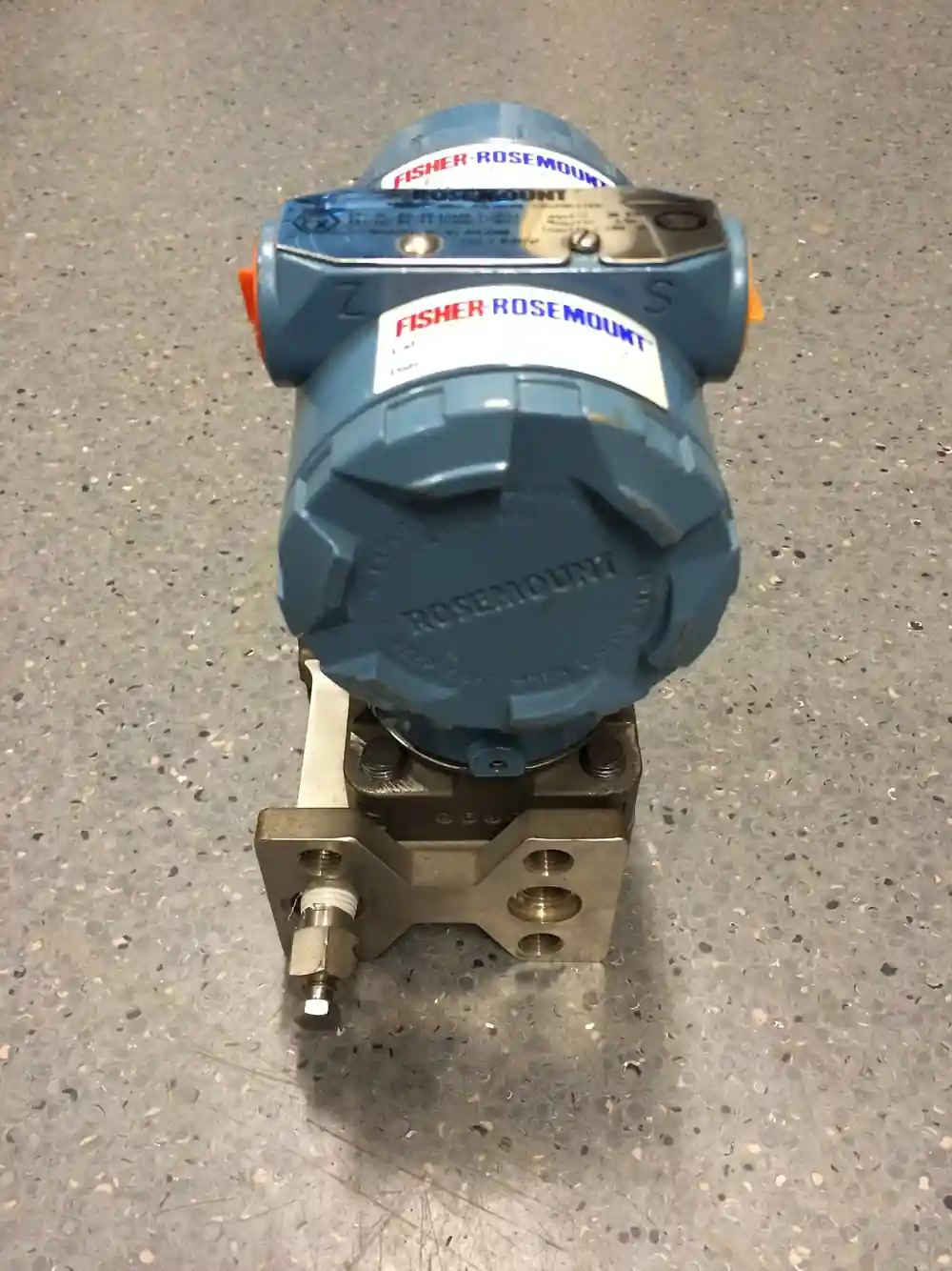
A condensate pot, also called a seal pot, condensate chamber, or sealing pot in maker catalogs, is a small pressure rated vessel installed in each of the two impulse lines between a steam flow primary element and the differential pressure transmitter that reads its output. The pot sits above the tapping point, live steam entering the line condenses inside it, and a stable column of condensate fills the leg from pot down to transmitter, forming a constant hydrostatic seal on both the high and low sides. Typical hardware is a forged body of 0.5 to 2 liters, a DN 50 to DN 80 barrel 150 to 300 mm tall, rated CL150 to CL2500, in A105 carbon steel or 316 and 316L stainless, with threaded, socket weld, or flanged connections. The rule the hardware serves is absolute: steam must never reach the transmitter body.
Procurement engineers meet these pots wherever steam flow is measured by differential pressure, on orifice plate flowmeter installations, on flow nozzle and averaging pitot tube jobs, and on venturi tube meter runs of saturated and superheated lines, because every one of those hookups dead ends at a transmitter full of oil and thin metal. The decision this page settles is narrow and practical: how large each pot must be relative to the impulse leg below it, what body material and class survive the steam chemistry, where the pair mounts relative to the pipe and the transmitter, and what commissioning and blowdown regime keeps the seal honest for years. The answer lands as an RFQ line set, pots plus valves plus tubing plus manifold specified together, because the pot bought as a loose fitting without its geometry is how steam installations drift.
This page treats the condensate pot as a purchasing object: the hydrostatics that make equal heads cancel, the volume arithmetic that keeps the leg alive through transients, the elevation and sloping rules that decide whether the reading is true, the materials and classes that survive wet steam, and the failure modes that show up as a drifting zero. It is written for engineers who issue purchase specifications and instrument installation drawings, not for readers who want a fitting catalog summary.
Chapter 1 / 06
What a Condensate Pot Is and What Is Being Decided
The condensate pot is protection hardware, and the thing it protects is expensive and delicate. A differential pressure transmitter for steam service costs one to two orders of magnitude more than the pot in front of it, and its measuring cell is filled with silicone oil behind diaphragms a few tenths of a millimeter thick. The cell is rated for static pressure, not for live steam temperature: saturated steam at 10 bar sits near 180 deg C, at 40 bar near 250 deg C, and either will cook the fill fluid, drift the zero, and eventually burst a diaphragm if the impulse line carries vapor instead of water. The pot exists so the line always carries water. Steam condenses in the chamber, the condensate column below it stands as a hydraulic barrier, and the transmitter sees a hot, stable, liquid-filled leg on both sides.
What is being decided in this purchase is therefore more than a vessel. First, the volume decision: the pot must hold 1.5 to 2 times the volume of the impulse line below it, per maker guidance, so the column never drains or flashes dry during transients and blowdowns. Second, the material decision: forged A105 carbon steel for clean saturated duty, 316 or 316L stainless where wet steam, carbon dioxide carryover, or condensate chemistry attacks carbon steel. Third, the class and connection decision: CL150 to CL2500 per ASME B16.34 pressure class logic, with NPT, socket weld, or flanged ends matched to the plant's tubing and valve standards. Fourth, the geometry decision, made on the instrument installation drawing long before purchase: both pots at the same elevation, above the taps, above the transmitter, with lines sloping down. A quotation that answers only the vessel and not the geometry is a fitting sale, not a measurement protection scheme.
The pot also lives in a hardware chain, and the chain belongs in the same purchase order. At the tapping point, a root valve, gate or needle pattern in class 800 or the line class, isolates the whole leg. Between root valve and pot, and between pot and transmitter, runs 12 mm or 1/2 inch OD stainless tubing assembled with compression type tube fitting joints, sloped and supported. At the transmitter, a three or five valve instrument manifold provides equalization and venting for zero checks. At the pot bottoms, drains serve blowdown duty. Each of these components has its own leaf in this encyclopedia; this page covers the pot itself and the hookup practice that makes it work.
Boundaries should be stated at the start, because the pot is often asked to do jobs that belong to other hardware. The condensate pot is the steam specific solution: it exists to manage condensate on steam impulse lines, and it is the balanced pair arrangement for differential duty. It is not the small syphon or pigtail coil used ahead of a pressure gauge, and it is not the isolation strategy for corrosive or freezing fluids, both of which belong to other protection hardware discussed in the selection chapter. Plants that confuse these three buy the wrong drawing, and the wrong drawing is what this page exists to prevent.
Compressed to one sentence, the decision is whether the steam flow hookup is bought as a system, pot pair sized to the legs, valves and manifold and tubing specified with it, elevations surveyed at installation, and commissioning performed hot, or as two loose vessels threaded onto whatever piping was nearest. The chapters that follow supply the hydrostatics, the sizing arithmetic, the materials, the drawing rules, and the failure modes needed to specify it the first way.
Chapter 2 / 06
How the Condensate Seal Works
The mechanism is condensation plus gravity, and it is worth walking through once because every installation rule follows from it. Live steam enters the pot from the tap through the root valve; inside the chamber, the steam meets the cooler pot wall and the water already there, gives up its latent heat, and condenses. The pot sits above the tapping point and above the transmitter, so the water produced falls and fills the pot, then the leg below it, right down to the transmitter ports. Steam continues to arrive at whatever rate the leg loses heat, condenses at the top surface of the water column, and the system reaches a steady state: a self refilling, constant temperature hydraulic seal whose only job is to be the same on both sides.
The arithmetic that makes the seal invisible to the measurement is the heart of the method. Each leg adds a pressure at the transmitter equal to the condensate density multiplied by gravity multiplied by the height of the column: at a hot condensate density near 920 kg per cubic meter, every meter of leg adds about 9 kilopascals. When the high and low legs are identical in height and identical in fill, the two hydrostatic heads are equal, equal heads cancel in a differential measurement, and the differential pressure transmitter reads only the process differential produced by the primary element. The seal is thus transparent by symmetry rather than by calibration, which is why the arrangement survives decades without adjustment, and why the symmetry is the specification.
Break the symmetry and the error is immediate and permanent. If one pot sits 100 mm lower than the other, the taller column adds extra head equal to 0.1 m times 920 kg per cubic meter times gravity, which is about 0.9 kilopascals. On an orifice installation spanning 10 kilopascals at full flow, that is a 9 percent error applied to every reading, fixed, silent, and indistinguishable from a calibration offset until someone surveys the elevations. A 300 mm error, entirely possible when pots hang off unsupported tubing, is 2.7 kilopascals and more than a quarter of span. This is the classic commissioning failure of steam hookups, it cannot be trimmed out honestly at the manifold because it scales with condensate density and therefore with steam pressure, and it is why the drawing states a level tolerance and the installer surveys it.
Orientation of the steam line changes the drawing, not the principle. On horizontal steam lines, both taps sit on or above the horizontal centerline, and both pots mount at the same elevation above them, so condensate always runs downhill from pot to tap and from pot to transmitter. On vertical steam lines the taps separate vertically, and the practice is to mount both pots at the elevation of the upper tap or above it, with the leg to the lower tap arranged so it stays water filled; the goal is unchanged, equal columns at equal temperature, and the condensing pot pair is positioned to guarantee it. Superheated steam adds a condensing distance problem: the steam is hotter than saturation, gives up superheat before it condenses, and makers answer with extra pot volume or a longer condensing leg so vapor never reaches the far side of the chamber; saturated steam lines between 150 and 250 deg C, the common industrial band, condense readily and follow the standard sizing.
The piping between pot and transmitter is part of the seal. Impulse tubing slopes continuously downward from pot to transmitter at roughly 1 in 10, 100 mm of drop per meter of run, so any gas that finds its way in travels back up to the pot rather than collecting as a pocket; a gas pocket in one leg is a shorter water column and a false differential, exactly the error the sloping exists to prevent. Tubing runs are kept short, straight, and supported, bends are gentle, and the whole leg is insulated or heat traced to the climate's demand so the condensate neither freezes in winter nor flashes in summer. Where the transmitter must sit above the pot for drainage or access reasons, the design changes character and belongs on a reviewed drawing, not on site improvisation.
At the transmitter end, the seal meets the manifold. Zero checks and equalization happen through the three or five valve instrument manifold, with equalize and block sequences that compare the two legs without opening either to atmosphere; the five valve version adds a drain pair for venting to a safe location. Commissioning and blowdown procedures use the drain path: the root valve closes, the pot and leg drain through a needle valve at the pot bottom to clear scale and debris, then the pot refills with clean water or condensate before the line returns to service. The zero that matters is taken at operating temperature and pressure, after both legs have reached thermal equilibrium, because a cold zero and a hot zero differ by exactly the head and density physics this chapter has been describing.
Chapter 3 / 06
Types, Construction, and Duty Boundaries
The catalog variety is smaller than for valves, and the choices are real. Bodies are forged, not cast, because a forging in impulse service is the conservative answer to pulsation and thermal cycling: forged A105 carbon steel for dry saturated steam on carbon steel lines, 316 or 316L stainless for wet steam, chemical carryover, and clean steam duty, with alloy alternatives quoted for aggressive refinery service. Pressure classes run CL150 to CL2500, so the pot matches the steam line's ASME B16.34 pressure class context rather than the instrument's rating, which is far lower. End connections are 1/2 inch FNPT, socket weld, or flanged; a flanged pot with a spiral wound graphite filled gasket suits high class and biannual inspection regimes, while threaded and welded pots dominate routine work because they are cheaper and simpler to support.
Internally the pot is deliberately boring: a plain cylindrical chamber, a top connection or plugged opening for filling and venting, a side or bottom tap for the impulse connection from the steam line, and a bottom or lower side drain. What varies is the interface hardware. The modern standard is 12 mm or 1/2 inch OD stainless tubing with compression tube fitting joints from pot to manifold, because tubing flexes with thermal growth, supports easily, and drains cleanly; plants with heavier standards run small bore pipe with welded pipe fitting joints instead, trading flexibility for rigidity and a hot work permit at every modification. Both are legitimate; mixing them on one leg is not, because the drain and slope geometry differ.
Maker catalogs organize the hardware differently and the RFQ should name the pattern. AS-Schneider lists condensate pots within its needle type globe valve and accessory families, sized and rated for steam metering hookups. Swagelok's instrument manifold systems catalog covers the seal pot as part of the tubing to transmitter chain, manifold and valves specified as one assembly. Delta Fluid's condensation pot datasheet gives the European dimensions and ratings. Drain assemblies range from a simple plug to a needle valve to a double block and bleed valve arrangement where blowdown must be positive and the vent routed; the choice follows the plant's steam pressure and safety practice, not price. The comparison table below compresses the construction decision.
Gasket retorque after thermal cycling; flange alignment and bolt torque discipline
Pot with integral drain needle valve
Per body class
Blowdown practice on scaling steam
Drain routing to safe location; valve seat wear from scale
Pot with double block and bleed drain assembly
Per body class
Positive isolation for blowdown at higher pressure
Complexity and cost; only where practice demands it
Duty boundaries close the chapter. The condensate pot is not a chemical barrier: if the process fluid is corrosive to the transmitter's wetted parts even as a cooled condensate, or so viscous it plugs small bore tubing, or prone to freezing in a way tracing cannot manage, the pot is the wrong tool and the selection chapter names the right one. The pot is also not a pulsation damper, a snubber, or a flow element; it is a condensate management vessel, and steam metering is its whole job. Nor does it care which primary element feeds it: an orifice plate flowmeter, a flow nozzle, a venturi tube, and an averaging pitot tube all end in the same pair of condensate filled legs, and the only things that change between them are the tap geometry on the drawing and the differential span on the transmitter, which the selection chapter treats in detail. Finally, single ended duty exists: a sealing pot on a static pressure impulse line ahead of a gauge or transmitter is a real but lighter duty, sized by the same volume logic without the paired equal head requirement, and the datasheet should say which duty the vessel is bought for.
Chapter 4 / 06
Key Specification Parameters
The datasheet rows below decide whether a quoted pot matches the service; values are stated as the common industrial span across the maker catalogs, with every row confirmed against the specific datasheet before order.
Attribute
Typical range or options
What it decides
Volume class
0.5 to 2 L; 1.5 to 2 times the impulse line volume below the pot
Whether the seal survives transients and blowdown without draining or flashing
Body size
DN 50 to DN 80 barrel, 150 to 300 mm tall
Mounting footprint, holdup volume, and support design
Body material
Forged A105; 316 or 316L stainless
Survival against wet steam chemistry and condensate corrosion
Pressure class
CL150 to CL2500 per ASME B16.34 pressure class context
Match to the steam line rating, not the transmitter rating
End connections
1/2 inch FNPT, socket weld, flanged
Interface to plant tubing or piping standard and inspection regime
Temperature capability
Saturated band 150 to 250 deg C common; higher with class and material
Condensation behavior and gasket selection at the pot joint
Fill and drain provisions
Top plug or flange for filling and venting; bottom drain
Commissioning fill, blowdown practice, and refill time
Drain valve pattern
Plug, needle valve, or double block and bleed assembly
Positive blowdown isolation and safe vent routing
Certificates
Material certificates EN 10204 3.1, hydrotest per class
Traceability for the pressure retaining weldment
The volume row deserves its arithmetic, because it is the sizing decision. Count the impulse line below the pot: 10 meters of 12 mm OD tubing with a 8 mm bore holds about 0.5 liter, computed as bore area times length, and 20 meters holds about 1 liter. The pot must hold 1.5 to 2 times that volume so the column survives a transient, a partial drain, or a boil off event without the level leaving the chamber; a 1 liter pot serves the 10 meter leg with margin, while the 20 meter leg gets the 2 liter class. Refill behavior follows the same numbers: after a controlled blowdown, steam condensing in the chamber restores the column in minutes at saturated conditions, and the commissioning procedure simply waits and verifies rather than forcing the issue. Oversizing costs mounting space and slow thermal equilibrium; undersizing costs the transmitter.
Installation parameters belong on the datasheet and the installation drawing together, and the table below states the practical spans and the reasoning that connects them.
Installation parameter
Practical span
Design logic
Pot elevation relative to taps
At or slightly above the horizontal centerline of the steam pipe
Steam rises to the pot, condensate falls back; the seal establishes itself
Elevation parity of the pair
Level within about 10 mm; surveyed at installation
100 mm offset at 920 kg per cubic meter condensate is about 0.9 kPa of fixed error
Pot to transmitter height
Pots above the transmitter; legs of similar length
Equal heads cancel; the transmitter stays in the cool zone
Impulse line slope
About 1 in 10, 100 mm drop per meter, continuous
Gas returns to the pot instead of pocketing in the leg
Tubing size and support
12 mm or 1/2 inch OD stainless, supported every 1 to 1.5 m
Sag pockets collect gas; unsupported runs move the pots off level
Freeze protection
Insulation, self limiting heat trace, or traced enclosure by climate
A frozen leg reads zero differential with complete confidence
The companion instrumentation rows complete the specification, because the pot protects a measurement that other instruments finish. Steam temperature at the meter run, read by a temperature transmitter on an RTD PT100 element in a thermowell, feeds the density computation that turns differential into mass flow, and the same reading tells the engineer what condensate density to expect in the legs. Static pressure at the tap, read by a pressure transmitter or, where the design calls for absolute units, an absolute pressure transmitter, completes the density compensation; on steam those readings are not accessories, they are the difference between a differential number and an engineering unit. Where the primary element is a high beta flange tap arrangement, the tap flange drilling and the pot connection standard must agree from the first drawing, and the impulse takeoff orientation must let the pot sit where the elevation rules put it.
Chapter 5 / 06
Selection Decision Factors and RFQ Language
The selection sequence runs as a checklist, and each line eliminates a class of errors before the purchase order exists.
State the steam condition honestly: saturated or superheated, pressure and temperature band, wet steam likelihood, and the chemistry that decides between A105 and 316L.
Name the primary element and its tap geometry: an orifice plate flowmeter with flange or corner taps, a flow nozzle, an averaging pitot tube, or a venturi meter run, because span and tap placement set the pot placement.
Compute the leg volumes from the real tubing runs, then select pot volume at 1.5 to 2 times leg volume, rounding to the nearest catalog vessel.
Fix the drawing geometry: both pots at the same elevation at or above the tap centerline, above the transmitter, legs sloping at about 1 in 10, supports and trace specified.
Fix the hardware chain: root valves at the taps, tubing and fittings, manifold pattern at the transmitter, drain arrangement at the pots.
Fix the commissioning and blowdown procedure, including the hot zero at operating temperature and pressure.
Fix the verification regime: elevation survey at install, zero checks quarterly to annually by duty, blowdown schedule on scaling steam.
Add the compliance lines: material certificates, hydrotest evidence, and pressure class documentation per the plant's piping code practice.
Against the neighboring protection hardware, the condensate pot holds specific ground, and the comparisons belong here in the selection chapter rather than in the page title. For corrosive fluids, polymerizing liquids, and services that would freeze in a small bore line, the industry answer is a diaphragm seal: a flexible metallic diaphragm at the tap isolates the process, and a capillary filled with stable fluid transmits pressure to the transmitter with no condensate column to manage at all. A diaphragm seal with capillary solves problems the pot cannot, at the price of temperature effects and elevation sensitivity along the capillary; the pot solves the steam problem specifically, cheaply, and with better than capillary accuracy, which is why steam hookups stay with pots. For a single pressure gauge on a steam line, the small syphon, the pigtail or coil loop that holds a static condensate plug, is the right and much cheaper answer; the pot is the larger, balanced, pair arranged instrument for differential duty and should not be reduced to a gauge accessory. Within the primary element choices, the pairing logic differs: a venturi tube or a flow nozzle on high energy steam produces a large differential with clean pressure recovery and its taps still need the pot pair, while an averaging pitot tube on a large duct produces a small differential, a few kilopascals of span, and the pot elevation parity tolerance must tighten accordingly, because a 0.9 kilopascal head error that is noise on a 25 kilopascal orifice span is fatal on a 5 kilopascal averaging span. The same instrument skid often carries a sample conditioning system for steam or water chemistry analysis, and the disciplines rhyme: both extract a process condition through small bore hardware that must stay flowing, clean, and honest.
The application map below compresses the practice into the form a project file carries.
Application
Typical construction to specify
Check before order
Saturated steam orifice metering, 10 to 40 bar
Forged A105 or 316 pot pair, 1 to 2 L, class per line, threaded or socket weld
Leg volume arithmetic; elevation parity survey; hot zero procedure
Superheated steam flow nozzle installation
Larger volume pots or extended condensing leg, 316L, high class flanged
Condensing distance above superheat; flange and gasket spec at class
Wet steam with carbon dioxide carryover
316L stainless pots and tubing, stainless root valves
Condensate chemistry against carbon steel; corrosion allowance honesty
Averaging pitot tube on large steam duct, low span
Standard pot pair with tightened level tolerance, short equal legs
0.9 kPa per 100 mm arithmetic against the actual span
Outdoor installation in freezing climate
Pots and legs insulated and heat traced, traced enclosure for the transmitter
Trace circuit supervision; winter zero checks after cold snaps
Legacy plant upgrade of drifting steam flow loop
Replace pot pair, re-plumb legs to slope, add manifold and survey
Old drawings versus actual elevations; span versus fixed head error
The RFQ block should be written once and reused: quantity, two pots per differential hookup; volume class with the leg volume computation attached; body material and pressure class per the steam line; end connections matching the plant standard, tubing with compression fittings or small bore welded pipe; fill, vent, and drain provisions; drain valve pattern from plug to needle valve to double block and bleed assembly by plant practice; certificates, material to EN 10204 3.1 and hydrotest evidence; the instrument installation drawing showing elevations, slopes, supports, and tracing; and the commissioning requirement, fill and blowdown procedure plus zero verification at operating temperature and pressure. A quotation returned without the volume basis or the class documentation is incomplete at any price.
Chapter 6 / 06
Installation, Standards, Failure Modes, and Maintenance
Installation quality decides whether the seal ever worked. Set both pots at the same elevation, at or slightly above the steam pipe centerline and always above the transmitter, and survey the pair with a level rather than a tape and judgment; the drawing tolerance is tight because the arithmetic in chapter 2 is unforgiving. Run the impulse tubing from pot to manifold in 12 mm or 1/2 inch OD stainless with compression tube fitting joints, sloping continuously at about 1 in 10 with no sags and no pockets, supported often enough that the tubing cannot creep the pots off level. Where the plant standard is welded small bore pipe with pipe fitting joints instead, keep the same slope and support discipline and accept the hot work cost at installation and every later modification. Support the pots themselves from steel, not from the tubing, and keep the transmitter below them in the cool zone, mounted and vented per its own installation practice.
Commissioning is a procedure, not a moment. Fill both pots with clean water or open the root valves and let steam condense slowly with vents open, so the legs fill without slugs and trapped gas. Blow down each leg in turn: close the root valve, drain the pot and leg through the bottom needle valve to clear scale and construction debris, close the drain, and refill before returning the leg to service. Bring the line to operating pressure and temperature, let both legs reach thermal equilibrium, then zero the transmitter through the three or five valve instrument manifold with the equalize sequence, and record the hot zero. A zero taken on a cold system is a number from a different physical machine; the condensate density and the leg temperatures that the measurement depends on simply are not the same until the system is hot.
The standards frame assembles honestly, because the pot itself is governed by pressure part practice while the hookup is governed by measurement practice. Body ratings and wall thickness follow the ASME B16.34 pressure class context, material certificates follow EN 10204 practice, and gauge related context draws on ASME B40.100. The impulse line and signal transmission practice that governs how the legs are run is the honest citation: ASME PTC 19.5, the flow measurement performance test code's instrumentation volume, and ISO 2186, the standard for transmission of pressure signals by fluid filled lines, both cover elevation, slope, and seal arrangement for differential measurements on steam. Maker catalogs, the Swagelok instrument manifold systems catalog's seal pot sections, the AS-Schneider condensate pot families, and the Delta Fluid condensation pot datasheet, carry the dimensional and volumetric specifics that the standards leave to the manufacturer. Citing all of these in the RFQ moves the burden of proof to the supplier, where it belongs.
Failure modes in service follow a short and predictable list. A drained pot, from blowdown left open or a leak, lets steam reach the transmitter: the symptom is an erratic or shifting zero and a transmitter housing hot enough to warn a hand held near it, and the remedy is the refill procedure plus a leak search along the leg. Unequal pot heights produce the fixed span error computed in chapter 2: found by survey, fixed by re supporting, and never honestly trimmed out at the manifold because the error scales with condensate density. Tap and leg plugging with silica and magnetite scale starves a leg: blowdown practice clears it, and the drain assembly, from needle valve to double block and bleed valve arrangement by pressure, is what makes that practice possible. Freezing in cold climates blocks a leg silently: insulation and heat trace, with circuit supervision, are the prevention, and a post cold snap zero check is the detection. Corrosion of carbon steel pots on wet steam thins walls over years: the stainless upgrade at the next replacement is cheaper than the failure investigation. Gasket leaks at a flanged pot joint announce themselves as wet streaks after thermal cycles: retorque per the bolt torque table at the first outage, replace the gasket on any recurrence. And the companion instruments that complete the measurement deserve the same schedule discipline, a temperature transmitter audit and RTD PT100 element verification per their own calibration intervals, plus a static check of the pressure transmitter or absolute pressure transmitter feeding the density compensation, because a steam mass flow number is only as good as the three instruments producing it, and the sample conditioning system sharing the skid follows the same quarterly logic the analyzer team already runs.
Maintenance is deliberately boring and mostly procedural. Blowdown on scaling steam service monthly to quarterly by water chemistry; zero check at operating conditions quarterly to annually by metering duty; elevation survey of the pot pair at every reinstall and after any adjacent piping work; heat trace and insulation inspection before each winter and after any maintenance that disturbed it; gasket and seal stock on the shelf, because a steam leak on a measurement leg is a shutdown argument if the spare is not there; and a log of hot zeros that turns every service event into a drift history. The throughline of this page is that the condensate pot is simple hardware carrying unforgiving arithmetic: bought to the volume rule, drawn to the elevation rules, and commissioned hot, it disappears into a measurement that holds its calibration for years, and skipped on any of those it becomes the single cheapest component responsible for the most expensive error on the meter skid.
FAQ
Where exactly must condensate pots be mounted?
Both pots mount at the same elevation, at or slightly above the horizontal centerline of the steam pipe, and always above the differential pressure transmitter, with the impulse lines sloping down to it at about 1 in 10. The pair must be level with each other within roughly 10 mm, surveyed with an instrument, because each 100 mm of height difference adds about 0.9 kilopascals of fixed error at hot condensate density. Support pots from steel, never from the tubing.
How is condensate pot volume sized?
Count the impulse line volume below the pot, bore area times length: 10 meters of 12 mm OD tubing with an 8 mm bore holds about 0.5 liter, 20 meters about 1 liter. Select a pot holding 1.5 to 2 times that volume, per maker guidance, so the condensate column survives transients and blowdowns without draining or flashing dry. Catalog vessels of 0.5 to 2 liters cover most legs, and refill after blowdown takes minutes.
What is the commissioning procedure for a pot pair?
Fill both pots with clean water or let steam condense with vents open so the legs fill without gas slugs. Blow down each leg in turn, closing the root valve, draining through the bottom valve to clear scale, and refilling. Bring the line to operating pressure and temperature, wait for thermal equilibrium, then zero the transmitter through the manifold and record the hot zero. A cold zero belongs to a different physical system and will not repeat.
Why must both pots sit at exactly the same elevation?
Each leg adds head equal to condensate density times gravity times column height, and the measurement works because equal heads cancel. A 100 mm elevation difference at a hot condensate density near 920 kg per cubic meter is about 0.9 kilopascals, which is 9 percent of a 10 kilopascal orifice span and worse on low span averaging installations. The error cannot be trimmed out honestly because it scales with condensate density, so it is fixed only by leveling.
When should I use a diaphragm seal instead of a condensate pot?
Use the pot for steam: it is cheap, accurate, and self refilling. Use a diaphragm seal with capillary when the fluid is corrosive to transmitter wetted parts even after cooling, polymerizes or plugs small bores, or freezes in ways tracing cannot manage. The seal trades the condensate column for fill fluid and capillary temperature effects, and it costs more. For a single pressure gauge on steam, a small pigtail syphon is the right accessory, not a pot pair.
Carbon steel or stainless pot bodies?
Forged A105 carbon steel serves dry saturated steam on carbon steel lines and dominates routine installations on cost. Move to 316 or 316L stainless when the steam is wet, when carbon dioxide or amine carryover makes the condensate aggressive, or on high class duty where the wall arithmetic and inspection regime favor it. Carbon steel pots on corrosive condensate thin over years and fail the survey long before they fail the pressure boundary, so decide on chemistry, not price.
What maintenance does a steam flow hookup need?
Blow down the legs monthly to quarterly on scaling steam, take a hot zero quarterly to annually by metering duty, and survey pot elevations after any reinstall or adjacent piping work. Inspect heat tracing and insulation before winter, retorque flanged pot joints after thermal cycles, and stock gaskets and seal parts. Verify the temperature and pressure instruments feeding the density compensation on their own calibration intervals, since the steam mass flow number depends on all three.