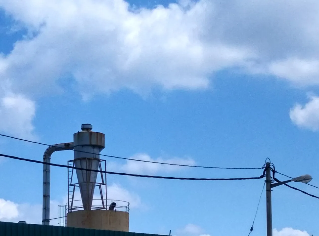
A rotary airlock is a slowly rotating valve that meters bulk solids out of a hopper while restricting gas flow between two zones at different pressures. Its working element is a cylindrical rotor with fixed vanes that divide it into pockets, turning inside a housing machined to running clearances of 0.1 to 0.5 mm. Solids fall into each pocket by gravity at the inlet and drop out at the bottom as the rotor turns, while the close clearances and the trapped pocket gas limit how much air passes up or down through the machine. Sizes run from about 100 to 800 mm inlet, rotor speeds from 5 to 30 rpm, and capacities from 0.01 to 200 m3/h depending on size, pocket volume, and speed.
Procurement engineers meet this machine at the bottom of nearly every dust collection and pneumaticconveying installation: under the hopper of a bag filter or cyclone dust collector, at the feed point of a dilute phase conveying line, and at metering stations for flour, plastic pellets, fly ash, and wood waste. The decision this page settles is narrow and practical: what size and speed actually deliver the required capacity at a realistic fill factor, how much air the valve will leak at the stated differential and where that air must be vented, which rotor and wear construction survive the material, and what the nameplate must say about ATEX categories and NFPA 69 isolation duty. The answer lands as an RFQ line set the chapters below assemble.
This page treats the rotary airlock as a purchasing object: pocket metering arithmetic with honest fill factors, clearance leakage behavior under differential pressure, drop-through and blow-through construction, wear packages for abrasive and sanitary duty, and how ATEX and NFPA 69 requirements are written into the nameplate and the RFQ. It is written for engineers who issue purchase specifications, not for readers who want a brochure summary.
Chapter 1 / 06
What a Rotary Airlock Is and What Is Being Decided
The machine is mechanically compact: a cast or fabricated housing with round or square inlet and outlet flanges, two end plates carrying bearings, a shaft seal at each end, and a rotor bolted to a shaft driven through a gear motor, usually direct coupled or chain driven. The trade knows it under several names that carry emphasis rather than difference. Rotary valve is the generic term; rotary feeder emphasizes the metering job, feeding a controlled volumetric rate to a process; airlock feeder and rotary airlock valve emphasize the pressure boundary job, holding a differential between a hopper at near atmospheric or slight vacuum and a conveying line or receiver at pressure. Nearly every industrial machine does both jobs at once, and pretending otherwise is where sizing mistakes begin, because the metering calculation and the leakage calculation pull the selection in different directions.
One disambiguation belongs in the first paragraph because it catches search traffic and purchase requisitions alike: in hydraulic circuits the phrase rotary valve names a directional control component that routes oil between ports of a rotating manifold, a fluid power product with its own standards world. This page is a bulk solids machine only. It moves powder and granular material between pressure zones, contains no hydraulic function, and shares nothing with hydraulic valve hardware beyond two words of vocabulary. Buyers writing specifications for solids handling should title the line item rotary airlock or rotary valve for solids service so the procurement system does not misroute it.
What is actually being decided in this purchase is a set of coupled commitments made in one purchase order. The size and speed commitment fixes capacity, but only jointly with a fill factor the buyer must state, because catalog capacity at 100 percent fill is a fiction no material delivers. The leakage commitment fixes how much conveying or draft air crosses the valve and therefore the size of the vent line, the conveying blower margin, or the dust collector draft loss. The rotor commitment, open or shrouded, fixed or adjustable tips, straight or offset inlet, decides how the material survives the machine and how the machine survives the material. The construction commitment, cast iron or stainless, standard or wear protected, plain or jacketed, sets the maintenance interval. The compliance commitment, ATEX category and NFPA 69 isolation certification on combustible dust duty, decides which suppliers can quote at all. A quotation that answers only size and rpm has answered none of these.
In a working plant the rotary airlock sits at a junction of neighbors, and the station logic matters as much as the valve itself. Above it, a cyclone separator or a bag filter collects dust from an air stream and holds it in a hopper; the airlock meters that dust out continuously so the hopper never fills and blinding the collector. At the discharge side, the material may fall by gravity into a drum or day bin, onto a belt conveyor, or directly into a pneumatic conveyor line where blower air carries it to a silo. For on-off isolation of a full hopper, a knife gate valve is the honest instrument, because a rotary machine is never a gas-tight shutoff device. A screw conveyor can both meter and convey over a distance when no pressure boundary exists. The rotary airlock wins the specific combination: continuous volumetric metering across a pressure boundary at modest cost.
Five reference frames organize the datasheet. NFPA 652 requires the dust hazard analysis that determines whether the dust handled is combustible at all, and NFPA 654 extends the combustible dust housekeeping and equipment practice; both decide whether the valve needs any explosion-safety credential. NFPA 69 defines explosion prevention systems and, with it, the conditions under which a rotary valve serves as an isolation device against flame propagation between connected equipment. ATEX 2014/34/EU governs equipment intended for use in explosive atmospheres in the European market, with category markings that must appear on the nameplate. CEMA publications provide bulk handling design context for conveyors and feeders generally. For food and pharmaceutical duty, 3-A sanitary criteria and FDA-accepted material finishes decide whether a quick-clean construction is merely convenient or actually mandatory. A datasheet that quotes none of these frames on combustible or sanitary duty is a price tag, not a specification.
Chapter 2 / 06
How the Rotor Meters Solids and Holds the Pressure Boundary
Metering is volumetric arithmetic, and the buyer should run it before trusting any capacity curve. Displacement per revolution equals pocket volume multiplied by the number of pockets, and delivered capacity equals that displacement multiplied by rotor speed and by fill factor. Fill factor, the fraction of pocket volume actually occupied by material, runs 0.4 to 0.8 in honest practice: free-flowing pellets at modest speed approach the top of the band, fine or cohesive powders and high speeds sit near the bottom. Worked example: a mid-size valve displacing 8 L per revolution, running at 15 rpm with a fill factor of 0.6, delivers about 4.3 m3/h of material. Multiply by bulk density for mass rate, roughly 2.2 t/h on a 520 kg/m3 powder. The same valve at 25 rpm does not deliver two thirds more; fill factor falls as pocket dwell time at the inlet shrinks, and above roughly 30 rpm most materials fill so poorly that capacity gain flattens while wear and leakage keep rising.
The pressure boundary is maintained by geometry, not by seals. Between rotor tips and housing there is a running clearance, typically 0.1 to 0.5 mm diametral by maker and size, plus smaller axial gaps at the end plates. Gas crosses these gaps in proportion to the differential pressure and, for a fixed gap length, very steeply in gap width: doubling the clearance can more than double the leak because the flow area grows while the throttling length stays constant. Wear that opens a clearance from 0.15 to 0.40 mm therefore does not degrade the valve linearly, it degrades it catastrophically, and the symptom arrives upstream as conveying air starvation or collector draft loss. Differential ratings for conveying service commonly run to about 1 to 2.5 bar, the working band of dilute phase systems fed by positive displacement blowers; above that band the airlock is the wrong instrument and dense phase feeding hardware takes over.
Leakage arrives by two separate paths, and both must be budgeted. The first is clearance leakage just described: gas flowing through the running gaps from the high pressure side to the low pressure side. The second is displacement or carry-back gas: each pocket that discharges material at the bottom returns to the inlet filled with high pressure gas, which it releases into the hopper as it refills. Carry-back is proportional to displacement and speed and cannot be designed away; it is why even a brand new valve leaks measurably at zero wear. The combined leak volume must be vented somewhere, and the vent design is part of the purchase.
Unvented leakage is the classic self-inflicted failure. Gas released into the hopper flows counter-current to the falling solids, fluidizing fine material at the inlet so that pockets no longer fill, and it can pressurize a hopper that was designed for slight vacuum. Standard practice gives the valve a vent connection or vented inlet transition that returns the displaced gas, with its dust, to the hopper headspace or the dirty side of the dust collector, or to a small industrial filter on the vent line where the stream carries fines. The vent line needs a cross-section sized for the leak estimate with margin, and it must not be valved off to "fix" a dust problem, because the gas has no alternative path except backward through the material bed.
Two inlet architectures divide the family, and the choice follows the destination of the material. The drop-through valve has an inlet flange on top and an outlet flange on the bottom in line with the rotor; material falls through by gravity into a chute, a bin, a weighing hopper, or a downstream process. The blow-through valve builds the conveying pipe through the outlet side of the body: blower air passes continuously across the bottom of the rotor, stripping each pocket's contents into the air stream as the pockets open. The blow-through body is the standard feed device for dilute phase pneumatic conveyor systems, because it meters directly into the moving air without a separate transition hopper; the drop-through body is the standard discharge device under dust collectors and above process vessels, and it is the only architecture that works against a weighing scale because it discharges in discrete pocketfuls a load cell can integrate.
The physics at the inlet is not gentle, and material behavior decides how much machine you must buy. As each rotor tip sweeps past the inlet edge, material caught between the tip and the housing shear bar is cut or crushed before the pocket closes; fibrous and flaky materials wrap and wedge. Offset rotor designs move the inlet past the shear point so that pockets fill from the side as the tip retreats, trading a little capacity for dramatically less nip, which is why they are specified for flakes, prills, and friable pigments. Fine powders present the opposite problem, flushing: aerated powders flood through the valve faster than speed control can meter, and demand shallow pitch pockets, flexible wiper tips, or an upstream constriction.
Chapter 3 / 06
Types, Construction, and Duty Boundaries
The drop-through family covers most installed units. Round inlet drop-through valves are the commodity shape from about 100 to 300 mm, used under cyclones, small collectors, and day bins; square inlet valves from about 200 to 800 mm suit large bag filter hoppers and silo discharge, because the square opening matches the hopper outlet without a transition that could arch. Inlet sources vary as widely as the plants they serve: a valve may sit under a cyclone separator cone, under a storage silo, at the feed end of a process line, or at the head of a bucket elevator discharging into a pneumatic pick-up.
The blow-through family is defined by the conveying pipe through the body and exists almost entirely for pneumatic systems. Materials that blow through cleanly, pellets, granules, and coarse free-flowing powders, are its natural diet; fine powders that aerate can flood the line and usually meter better through a drop-through valve with a vented transition. The pressure boundary of a blow-through unit is set by the conveying system: dilute phase blower systems to about 1 bar differential are the center of the family, with reinforced constructions to about 2.5 bar for longer lines and stiffer materials.
Rotor architecture is where material behavior meets mechanics. An open rotor, with vanes welded between shaft and shroud at the ends only, passes lumps and stringy material and is easy to clean, but the open ends leak more and the vanes are less stiff. A shrouded or closed rotor carries full discs at both ends with vanes between, halving end leakage, stiffening the assembly for high differential, and suiting fine powders. Between these lie the specialty rotors: adjustable-tip rotors with replaceable blades that restore clearance after wear instead of scrapping the rotor; flex-tip rotors with polymer wipers for fine, non-abrasive powders where running clearance must stay tight; and offset or tangential rotors for shear-sensitive and sticky materials as described in chapter 2. Heated jackets around the housing hold hygroscopic and low-melt materials, brown sugar, certain pigments, some flaked resins, below their sticky point; the jacket must be specified with its medium and temperature, not just the word jacketed.
Construction classes follow the material and the regulator. Cast iron housings with steel rotors are the utility answer for inert mineral and wood dusts. Stainless steel, 304 for general food and 316L for chemical and corrosion duty, covers food, pharma, and chemical service, and in quick-clean or sanitary execution gives tool-less access to the rotor for cleaning between batches, with polished contact surfaces meeting 3-A criteria; the sanitary families of the major makers, the CI, QC, and RR series class, are built around exactly this access requirement. Wear packages double the life of abrasive service machines: Ni-hard or chromium carbide surfaced rotors and inlet chutes, ceramic tipped blades, and replaceable wear plates in the nip zone. On combustible dust duty the safety classes divide into containment constructions, whose housings withstand a defined internal explosion pressure, and isolation-certified constructions qualified under NFPA 69 as a flame barrier between connected vessels; the plant's dust hazard analysis decides which the line item must carry. Drive selection follows the area classification: an ordinary induction motor in a dust hazard location must be replaced by a suitable explosion proof motor with the matching temperature class for the dust in question.
Duty boundaries keep the family honest. The rotary airlock is never a gas-tight shutoff device: it passes clearance leakage by design and must not be counted on for personnel protection isolation, which belongs to locking out and blinding the line. It is not a pressure vessel and its differential limit is a hard ceiling, not a derate curve. It does not meter accurately with aerated, flushed, or heavily cohesive materials without upstream conditioning, and it cannot convey by itself: gravity or an air stream must remove what it discharges. The type table below compresses the family into the form a specification meeting argues from; values are common spans of the established families and must be confirmed against the model datasheet before order.
Type
Construction
Capacity and pressure class
Duty it wins
Round inlet drop-through
Cast iron or 304 stainless, open or closed rotor
100 to 300 mm, 0.01 to 20 m3/h, to about 1 bar differential
Cyclone and small collector discharge, day bin metering
Square inlet drop-through
Cast iron, stainless, or wear package; shrouded rotor
200 to 800 mm, 5 to 200 m3/h, to about 2.5 bar class
Large bag filter hoppers, silo discharge, batch weighing
Blow-through
Conveying pipe through body, pressure seals
100 to 400 mm class, dilute phase to about 1 to 2.5 bar
Feed of a pneumatic conveyor line from a hopper
Offset or tangential rotor
Inlet offset past the shear point
Mid family sizes, modest differential
Friable flakes, prills, sticky or shear-sensitive materials
Quick-clean sanitary
316L, polished, tool-less rotor access, 3-A criteria
Small to mid sizes, food and pharma pressure range
Food, pharma, and chemical batches cleaned between runs
Wear or containment class
Ni-hard or carbide trim, or rated containment housing
By size family; containment to a defined explosion pressure
The table below decodes the datasheet lines that decide whether a quoted valve matches the service. Values are stated as common spans of the established families and must be confirmed against the model datasheet before order.
Attribute
Typical range or options
What it decides
Inlet size and shape
100 to 800 mm, round or square
Hopper outlet matching, transition design, and capacity ceiling
Displacement per revolution
About 0.3 to 60 L/rev by size and rotor
Capacity arithmetic with speed and stated fill factor
Capacity at fill factor
0.01 to 200 m3/h at fill factor 0.4 to 0.8
Real throughput and the speed the valve must run to reach it
Rotor speed
5 to 30 rpm typical operating band
Metering resolution, wear rate, and fill behavior
Running clearance
0.1 to 0.5 mm diametral, stated at reference temperature
Leakage today and the wear budget before rebuild
Differential pressure rating
To 1 bar standard conveying, 2.5 bar reinforced class
Housing, rotor, and seal construction; blower system fit
Materials of construction
Cast iron; 304 or 316L stainless; Ni-hard or chromium carbide trim
Corrosion, product contact legality, and abrasive service life
Shaft seals
Lip seals, gland packing, air-purged or gas-purged seals
Dust containment at the shaft and maintenance interval
Drive package
Gear motor direct or chain, 0.37 to 15 kW family, with VFD
Metering control resolution and starting behavior
Compliance markings
ATEX category and temperature class; NFPA 69 isolation certification
Whether the valve may be installed on this dust at all
The displacement and fill factor rows deserve a paragraph together because they are where quotations become incomparable when left loose. A capacity quoted without a fill factor is a displacement figure wearing a capacity label; demand the displacement per revolution, pocket count, and assumed fill factor, then recompute the rate at your material's demonstrated fill behavior from a sample test or a reference installation. State the speed you expect to run: a valve sized to run at 8 rpm on abrasive fly ash survives several times longer than one speeded to 25 rpm because the next size up was cheaper, and the speed sets the metering resolution seen by any downstream gravimetric control. Where the process meters gravimetrically, the drive should be specified with a VFD from the outset, because volumetric pocket feeding alone drifts with bulk density changes of 10 to 20 percent that a gravimetric loop must trim out.
The clearance, differential, and leakage rows are one engineering argument in three lines. Demand the clearance as built at a stated reference temperature, the differential rating of the housing, and a leakage figure at a stated differential and temperature; if the maker offers only one of the three, the quotation is silent exactly where the risk lives, because leakage rises both with differential and with temperature as the rotor grows into the housing. The seal row matters more on fine powders than anywhere else: lip seals suit clean, low differential duty; packed glands take higher differential with adjustment; air-purged seals hold a barrier gas and suit both fine toxic dusts and combustible service where ingress must be controlled. The instrumentation that closes the station is cheap and standard, and the table below lists what belongs in scope, whoever supplies it.
Catches a failed filter element before emissions escalate
Drive control
VFD on the airlock gear motor
Metering trim and soft start instead of across-the-line
Area compliance
Explosion proof motor and bonding of the housing
Legal installation in a classified dust hazard area
What the datasheet must state, in plain terms: displacement per revolution and pocket count; speed range and the capacity basis including fill factor; clearance at reference temperature and the maximum operating temperature with its growth allowance; differential rating and leakage at stated conditions; housing, rotor, and trim materials with surface finish where product contact is regulated; seal type and purge requirements; drive rating, service factor, and control signal; vent connection size; and the complete compliance marking set, ATEX category and temperature class or NFPA 69 isolation certification, where the dust hazard analysis demands it. A quotation without the leakage basis or the fill factor basis is incomplete at any price, and those two omissions are the two most common ones on the market.
Chapter 5 / 06
Selection Decision Factors and RFQ Language
The selection sequence runs as a checklist, and each line eliminates a class of quotations before price comparison begins.
Characterize the material first: particle size distribution, bulk density, moisture, abrasiveness, cohesiveness, friability, melt or sticky point, and combustibility. Every later line depends on these answers, and a supplier who does not ask has quoted a catalog page, not a valve.
Compute capacity from displacement, speed, and a stated fill factor, then check the speed it implies; if the calculation wants more than about 25 to 30 rpm, select the next size up instead of speeding a small valve into poor fill and fast wear.
Fix the pressure boundary: hopper side pressure, discharge side pressure, their difference, and the temperature of both, because the housing class, the seal class, and the growth allowance all come from this line.
Choose the architecture: drop-through for gravity discharge, weighing, or process feeding; blow-through only where the material entrains cleanly into a dilute phase pneumatic conveyor line.
Choose rotor and tips against material behavior: shrouded for fine powders and differential, open for lumps, adjustable or ceramic tips for abrasive, flex tips for tight clearance on benign powders, offset for fragile flakes.
Specify the vent: size the vent line from the maker's leakage figure plus carry-back gas, route it to the hopper headspace, collector dirty side, or a dedicated filter, and forbid valving it off in operation.
Set the compliance line from the dust hazard analysis: ATEX category and temperature class, or NFPA 69 isolation certification, or containment construction, and the matching explosion proof motor drive for the area.
Fix the evidence: material certificates for product contact, leakage and capacity basis, clearance record, wear life statement with its assumed material and speed, and the maintenance and spares list.
Against neighboring equipment the rotary airlock holds specific ground, and the comparison belongs here in the selection chapter. A screw conveyor meters and conveys over tens of meters and seals reasonably well against low differential, but it cannot feed a pressurized conveying line economically and it works the material harder along its whole length; it earns its place when distance is part of the duty, not when the boundary is. A belt conveyor moves large volumes cheaply with no pressure boundary at all and no meaningful metering precision; it feeds a process, not a pressure zone. A knife gate valve isolates a hopper completely and cheaply but passes nothing while open in the throttling sense; on abrasive slurry-like duties a pinch valve gives tight shutoff with full bore passage, but both are on-off devices, and neither meters. A conventional gate valve suits general utility line isolation and belongs in the piping around the station, not under a hopper of moving dust. The rotary airlock is the only device in this list that combines continuous volumetric metering with a standing pressure boundary, which is exactly why nearly every dust collector in industry has one bolted to its hopper.
The application map below compresses the practice into the form a project file carries.
Application
Construction to specify
Check before order
Bag filter or cyclone hopper discharge
Drop-through, square inlet, cast iron or stainless, vented transition
Leakage vent routing and hopper level interlock
Dilute phase conveying feed
Blow-through with pressure-rated seals and shrouded rotor
Conveying differential and blower type stated in RFQ
3-A or FDA contact finish and cleaning access time
Friable flakes and prills
Offset rotor, reduced speed, larger size for gentle filling
Fill factor at low speed from a material sample test
Feed from a bucket elevator or silo
Drop-through with transition matched to the upstream outlet
Inlet headroom and transition angle against arching
The RFQ block should be written once and reused. A complete block reads: material name with particle size distribution, bulk density, moisture, and a stated abrasiveness and cohesiveness class; combustibility data or the dust hazard analysis reference; capacity in m3/h or kg/h at a stated fill factor and the speed assumed; hopper side and discharge side pressures with temperatures; architecture, drop-through or blow-through, and inlet size and shape; rotor type with tip specification and any wear package; housing, rotor, and trim materials with surface finish where regulated; shaft seal type with purge medium and consumption; drive with power, gear ratio range, and VFD scope; vent connection size and proposed routing; compliance marking set required; and the evidence list, displacement and capacity basis, leakage at stated conditions, clearance record, material certificates, and wear life statement. A quotation returned without the leakage basis and the fill factor basis is incomplete at any price.
Chapter 6 / 06
Installation, Standards, Failure Modes, and Maintenance
Installation quality decides whether the valve reaches its projected wear life. Mount the housing on flexible connections or a rigid spool that carries no hopper load, because a dust collector hopper that grows and shrinks with temperature will bend an airlock frame and close the clearances on one side. Align the drive chain or coupling within the maker's tolerance before guarding, and verify rotor rotation direction against the arrow, which sounds trivial until a reversed valve quietly meters at half rate with double shear. In a classified dust hazard area, the drive must be an explosion proof motor of the correct group and temperature class, the housing and rotor assembly must be bonded into the plant earthing grid with a measured resistance path, and the bonding jumper across each flexible connection must be installed, because an isolated rotor turning through a dusty dielectric is a static generator. Where the feed comes from a bucket elevator or a long chute, fit an inlet magnet or screen on tramp-metal-prone materials: one bolt can chip a ceramic tip and open a clearance permanently. Isolation above the airlock for rotor work is a knife gate valve or, on abrasive service, a pinch valve, and it should be exercised monthly so it works the day it is needed.
Instrument the station so it fails loudly instead of silently. A level switch high in the hopper stops feed-in before dust blinds the collector; many plants prefer a rotary paddle level switch there because it senses actual material, not a dielectric proxy, and gives a second low contact to stop the airlock running dry. A low level indication above the inlet also protects the rotor from running unlubricated by material on abrasive dusts. On the discharge side, a pressure transmitter on the conveying line gives the blockage trend that a hard-wired alarm cannot, rising slowly over days as the line, not the valve, degrades. On the collector itself, watch the differential across the filter element bank and keep a dust detector on the clean side; a dust detector catches a failed filter element within minutes instead of after the stack turns grey.
The standards frame is short but binding. NFPA 652 requires the dust hazard analysis that classifies the material and thereby the equipment duty; NFPA 654 sets the combustible dust practice for the facility around the valve; NFPA 69 governs the explosion prevention system in which a rotary valve may be credited as an isolation device, and the certification for that credit is a specific test and nameplate, not a marketing sentence. ATEX 2014/34/EU covers the European explosive-atmosphere marking, category and temperature class, and the EU declaration that must accompany the machine. CEMA bulk handling publications give the conveying context in which the valve is one component. For food and pharmaceutical contact, 3-A criteria and FDA-accepted finishes define cleanability, and the sanitary series of any serious maker documents exactly which of those criteria the model meets. Name the standards in the RFQ; the burden of proof then sits with the supplier, where it belongs.
Failure modes follow a short and predictable list. Rotor binding from temperature growth shows within hours of a hot startup: the rotor grows into the housing, the drive trips on overload, and the fix is a clearance specified for operating temperature rather than ambient. Abrasive wear opens the clearances over months; the valve still turns, but leakage climbs until conveying air starves or the collector draft collapses, and the honest countermeasure is a scheduled clearance measurement, not an emergency. Shaft seal wear announces itself as a dust streak below the drive end; lip seals are consumables, glands need adjustment, and purged seals need their barrier gas verified. Bridging above the inlet starves the valve on cohesive materials and is fixed upstream, with a wider transition, a steeper hopper, or a vibrating pad, never by speeding the rotor. Product degradation, chipped flakes and rounded prills, means the shear at the inlet is winning and an offset rotor is the answer. Static accumulation on an unbonded rotor is the silent one, which is why bonding verification belongs in the commissioning record and not in the accident investigation.
Maintenance scales with material severity and is budgeted in kits and clearances. Daily: a glance at the vent line for flow and at the shaft ends for dust. Weekly: hopper level behavior and conveying line pressure trend against the commissioning baseline. Quarterly: chain or coupling tension, seal adjustment where the design allows, and the dust detector function check. Annually or at the maker's interval: measure the running clearance with feeler gauges at the documented positions and compare with the as-built record; inspect rotor tips and replace adjustable blades while the clearance budget still allows setting; inspect the inlet shear bar and wear plates; verify bonding continuity; and service the vent filter if one is fitted, because an industrial filter in that service is cheap and a blocked one recreates the unvented failure. Hold spares against the duty: a seal kit, a set of adjustable tips on wear service, one complete rotor on continuous abrasive duty, and the drive bearings. Held to that rhythm, the station meters in its fifth year as it did in its first, and the clearance record turns the next RFQ into a specification written from evidence instead of hope.
FAQ
What is the difference between a rotary airlock and a rotary feeder?
In industrial practice the two names describe the same machine with different emphasis: rotary feeder stresses the metering function and rotary airlock stresses the pressure boundary, and most installed valves perform both at once. Some suppliers do distinguish: a feeder build may carry lighter clearances and seals for near-atmospheric duty, while an airlock build carries pressure-rated shaft seals and a housing certified for a stated differential. State the function that matters and the differential in the RFQ, and the naming question disappears.
How much air leaks through a rotary airlock and where does it go?
Leakage has two parts: gas flowing through the running clearances, 0.1 to 0.5 mm by design, and gas carried back inside each pocket to the hopper. Both grow with differential pressure, and clearance leakage grows steeply as wear opens the gap. The maker should quote leakage at a stated differential and temperature; that figure plus carry-back sizes the vent line, which routes the gas to the hopper headspace or the collector dirty side. An unvented airlock fluidizes its own inlet, so the vent is part of the purchase.
When do I need a drop-through valve and when a blow-through valve?
Choose drop-through whenever material leaves by gravity: into a bin, drum, chute, weighing hopper, or process vessel, most dust collector discharge included. Choose blow-through when the valve feeds a dilute phase pneumatic conveyor line directly: conveying air passes through the body and strips each pocket into the stream with no intermediate hopper. Blow-through suits pellets, granules, and coarse powders; fine aerated powders often flood a blow-through body and meter better through a drop-through valve with a vented transition. State the destination in the RFQ and the architecture chooses itself.
How do I size a rotary airlock correctly?
Run the arithmetic: displacement per revolution times speed times fill factor gives capacity, fill stated at 0.4 to 0.8 depending on the material. 8 L per revolution at 15 rpm and 0.6 fill gives 4.3 m3/h. If the duty needs more than 25 to 30 rpm to hit rate, choose the next size up, because fill collapses and wear accelerates at higher speeds. Then check the differential rating against the conveying or draft system and confirm leakage and venting at that differential before the order.
What rotor clearances are correct and when is a rebuild due?
Running clearance is 0.1 to 0.5 mm diametral, set at a reference temperature; hot service needs a larger cold clearance for growth room, so state operating temperature in the RFQ. A rebuild is due when measured clearance exceeds the maker's wear limit, when leakage degrades conveying or collector draft, or when adjustable tips can no longer be set. Measure annually with feeler gauges at the documented positions and trend against the as-built record; abrasive ash and sand erode clearances in months, gentle food duty holds them for years.
What do ATEX and NFPA 69 markings mean on an airlock nameplate?
ATEX 2014/34/EU marking states the equipment category and temperature class for explosive atmospheres, and must match the zone and dust from your hazard analysis; the area drive must carry a matching explosion proof motor marking. NFPA 69 is different: a valve credited as an isolation device against flame propagation must be certified to that function, a tested construction with defined clearances and length-to-diameter criteria, not any tight valve. Containment constructions that withstand an internal explosion are a third credential; ask which the nameplate carries before ordering.
Why does my airlock starve or plug on start-up?
Three causes. First, unvented leakage: pocket gas flowing into the hopper fluidizes fine material so pockets cannot fill; check the vent line is open. Second, bridging in the hopper above the valve on cohesive or moist material; the fix is upstream, a steeper transition, wider inlet, or flow aid, never a faster rotor. Third, a reversed rotor or a speed set above the material's fill band, both metering at a fraction of expected rate. Trend conveying line pressure and hopper levels, and the mechanism identifies itself within a shift.