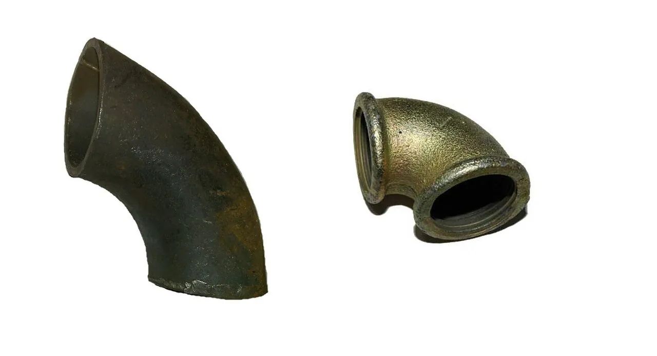
A tube fitting is the mechanical joint that carries instrumentation tube: a precision body with a threaded nut that swages a matched pair of ferrules onto the tube outside diameter, sealing metal to metal with no welds, no threads, and no sealant on the tube itself. The catalog runs from 1/16 to 2 inch outside diameter in fractional sizes and from 3 to 25 mm in metric, with working pressure set by the tube wall rather than by the fitting. Engineers meet it under several names: the instrumentation tube fitting label used in analyzer and impulse line work, and the compression tube fitting label inherited from older single ferrule hardware. This page is about the gaugeable dual ferrule class in the Swagelok MS-01-140 and HOKE Gyrolok tradition, and about the decisions that decide whether several hundred of these joints hold pressure for a decade.
What is actually being decided in this purchase is smaller than it looks and more consequential. The fitting itself is commodity hardware; the decision is the system: which tubing specification and wall, which fitting family, which end connections, and which installation discipline will be enforced across the whole plant. The RFQ line set that comes out of this page is short: tube material and specification with hardness, tube size and wall, fitting family and brand standard, body and ferrule material, end connection types with thread standards, certificates, and cleanliness level. A buyer who fixes those seven rows cannot be sold the wrong joint, and a contractor who receives them cannot improvise.
This page treats the tube fitting as a purchasing object: how the dual ferrule joint actually grips and seals, what gaugeability buys on a plant walkdown, which tubing specification carries the pressure basis, where the DIN 2353 bite type family begins and ends, and how all of it lands as RFQ language an installer cannot misread. It is written for engineers who issue purchase specifications, not for readers who want a brochure summary.
Chapter 1 / 06
What a Tube Fitting Is and What Is Being Decided
The standards situation is unusual and worth stating plainly: dual ferrule instrumentation fittings are manufacturer standards, not ISO dimensional standards. Swagelok documents its system in MS-01-140, HOKE in the Gyrolok catalog and installation manual, and the two are functionally equivalent but not interchangeable. The neighboring bite type family is dimensional: DIN 2353 fixes the 24 degree cone and cutting ring so hydraulic hardware from different makers interchanges. Adapter threads to the process world follow ASME B1.20.1 for NPT. Tubing follows ASTM A269 for seamless austenitic stainless steel and ASTM A213 for other alloys, and it is the tube specification, not the fitting brochure, that carries the pressure basis of the whole system.
Every fitting purchase sits inside a station, and the station belongs in the RFQ even when only the fittings are bought. At the process tap, root isolation is usually a small ball valve or a needle valve closed during instrument work. The impulse line then runs to a 3 valve or 5 valve instrument manifold at the transmitter: a pressure transmitter takes one line, while a differential pressure transmitter takes two legs to its manifold. Analyzer sheds add fast loop and sample return tubes on the same hardware. Whoever supplies the fittings should confirm tube schedule, manifold interface, and thread forms in one pass, because a mixed thread order is discovered at commissioning, never at purchase.
The commercial weight of the decision sits in the failure statistics, not the unit price. Instrument joints number in the thousands per unit, they carry hydrogen, hydrocarbon, and steam services, and they are assembled by hand at site. A joint under tightened by half a turn holds at the ambient test and weeps on the first hot cycle; a joint over tightened collapses the tube and cracks the front ferrule three shifts later. That is why the gaugeability discipline in chapter 2 and the failure catalog in chapter 6 are part of the purchase specification, not an installation footnote bolted on afterward.
Applications concentrate in five rooms of the plant: instrument impulse lines from process taps to transmitters, analyzer sample and fast loop systems, hydraulic and pneumatic control lines on skids, calibration and test benches, and utility drops to local panels. Each room has its own tubing size culture, 6 and 12 mm or 1/4 and 1/2 inch on impulse duty, 3 to 8 mm on analyzers, heavier metric walls in hydraulics, and each is covered by the parameter tables in chapter 4. The common thread is that the tube, not the fitting, defines what the system can hold, and that sentence alone settles more specification arguments than any catalog.
Procurement economics deserve one honest paragraph, because the unit price of a fitting is a rounding error next to the cost of handling it badly. A mid-size unit buys these joints in lots of several thousand across a construction project, and the failure mode of that scale is mixture: two brands on one job, ferrule bags separated from their bodies, and borrowed stock from the neighboring contractor. The countermeasures are cheap and boring: order bodies and ferrules from one supplier as matched kits, keep them in sealed bags until assembly, and issue the installation bulletin with the purchase order so the torque table travels with the hardware. A dollar of kit discipline per joint avoids the hundred dollar cost of finding one leak inside an insulated panel during startup.
Chapter 2 / 06
How the Dual Ferrule Joint Grips and Seals
The joint works in two operations. As the nut turns, it pushes the ferrule assembly into the converging mouth of the fitting body. The front ferrule, a precision ring with a shaped nose, is squeezed between the nut and the body bevel; its nose rolls onto the tube and creates two sealing interfaces, one against the body bevel and one on the tube outside diameter. Behind it, the back ferrule with its hardened cantilevered rear edge bites into the tube surface as the nut drives it forward. The front ferrule seals; the back ferrule grips, resisting axial pullout and the micro motion of vibration for the life of the joint.
Assembly numbers are published per size and must be quoted per brand. The sequence: insert the tube until it bottoms on the shoulder, tighten the nut finger tight, mark the nut at six o'clock with a scriber, then tighten with a wrench to the table. For the gaugeable dual ferrule systems the table reads 1-1/4 turns for the 1/16 through 1/2 inch sizes and 1 turn for 3/4 to 1 inch, with metric tables mirroring the same classes. Swagelok and HOKE Gyrolok values are close but not identical, and the assembler must tighten to the table of the brand actually in hand. Two wrenches are mandatory, one on the nut and one backing the fitting body, so that torque does not reach the adjacent tube bend and spring every joint upstream of it.
Gaugeability is the inspection right that separates this class from generic compression hardware. After make up, a go no go gap gauge for the specific size slips between the nut hex and the body hex: if the gauge enters, the nut has not driven the ferrules and the joint is under tightened. The same gauge arbitrates remakes. On disassembly the ferrule set stays swaged on the tube and travels with it; reassembly seats the preformed ferrules and adds roughly a quarter to half a turn past the shoulder, per the vendor manual. A ferrule set that has slipped axially, or a tube scored under the front ferrule, is a replacement item, not a candidate for another half turn of hope.
Pressure capability is tube mechanics, and stating that honestly is half the specification. In words: a thin walled cylinder under internal pressure carries hoop stress proportional to pressure times diameter divided by wall, so burst pressure scales with twice the tensile strength times the wall divided by the diameter, and vendor working pressures sit at roughly a 4:1 margin below burst. Seamless 316 stainless steel tube at ambient works to about 190 bar at 1/4 inch outside diameter with 0.020 inch wall, about 340 bar at 0.035 inch wall, and about 235 bar at 1/2 inch with 0.049 inch wall. Smaller outside diameter raises the rating and larger diameter lowers it at equal wall. The fitting body is rated at or above the burst of the matched tube, so the tube governs every time, and heat derates it further.
Temperature envelope is a materials question: the fitting system spans minus 254 deg C in cryogenic service to about 540 deg C with high temperature materials and disciplined practice, with the real limit set by the tubing specification. Vibration performance is where the back ferrule earns its cost. A threaded joint walks loose because friction is its only holding mechanism and thread sealant cold flows under thermal cycling; the bite of the back ferrule is mechanical keying, and it holds grip through vibration spectra that shake threaded hardware apart within weeks. That is the engineering reason impulse lines are tube, and the reason this fitting, rather than any threaded joint, terminates at the transmitter.
Chapter 3 / 06
Types, Construction, and Duty Boundaries
Three families cover the field. The dual ferrule instrumentation fitting of this page runs fractional and metric instrument tube from 1/16 to 2 inch and is the default wherever measurement, sampling, and clean fluids meet small bore piping. The DIN 2353 bite type compression fitting cuts a single ring onto metric tube against a standardized 24 degree cone, in LL, L, and S series, working to the 420 bar class at small sizes; it is the hydraulic world standard on carbon and stainless metric systems. Single ferrule brass fittings serve low cost air and water duty at modest pressure. The selection chapter draws the boundaries between them; the rule in this chapter is that families never interbreed, because neither body geometry nor assembly table transfers.
Body materials follow service. 316 stainless steel is the default for chemical, steam, and analyzer work; brass carries instrument air at low pressure; carbon steel serves hydraulic systems; Hastelloy C276, Monel 400, and titanium cover wet chlorine, seawater, and specialty duty. Configuration is half the RFQ: unions join tube to tube in straight runs; union elbows and tees turn and branch without fabricated bends; male and female connectors terminate on threads; reducers change size between runs; instrument root and gauge isolation is served by needle valve bodies in the same fitting system. Adapter ends are NPT per ASME B1.20.1 or ISO parallel threads, and where a tube system meets a flanged line, a flange adapter closes the transition with a gasket on the raised face flange, and that gasket belongs on the same order so facing finish and pressure class are matched in one delivery.
The tube is the pressure boundary and the grip surface, so its specification is not optional. The default call is seamless ASTM A269 316, fully annealed, at about Rb 80 hardness, the dead soft condition in which the back ferrule can bite and the front ferrule can seal. Welded and redrawn tube is acceptable where the manufacturer list admits it. Tube harder than the class lets the back ferrule skate instead of bite: the joint passes a cold hydrotest and then loses grip under vibration, which is the most deceptive failure in this hardware. Hardness, heat number traceability with EN 10204 3.1 certificates, and wall tolerance belong in the tube purchase line, not in the fitting footnote.
Duty boundaries keep the families honest. Impulse lines to transmitters are the home territory: low volume, high reliability, sized at 6 and 12 mm or 1/4 and 1/2 inch. Analyzer sample systems add dead volume and inertness constraints that favor the same hardware in smaller sizes. Hydraulic power units on the DIN side see 100 to 315 bar with pressure spikes above nominal. Instrument air below 10 bar belongs to lighter hardware. Above roughly 1000 bar the gaugeable systems end and cone and thread fittings, the legacy high pressure standard, take over with their own coned tube end practice. Oxygen and high purity services add cleaning requirements to whichever family is chosen, and those requirements are certificates, not promises.
The duty map below compresses those boundaries into the form a specifier carries into a review meeting.
Service
Construction to specify
Check before order
Steam and hydrocarbon impulse lines
316 stainless steel dual ferrule, seamless ASTM A269 tube, 6 or 12 mm
Heat derate of tube rating; supports and slope plan
Analyzer fast loops and sample lines
316 stainless steel or alloy, low dead volume configurations
Surface inertness and cleaning level required
Hydraulic power units, 100 to 315 bar
DIN 2353 L or S series on metric steel tube
Spike pressure above nominal; cutting ring seating check
Instrument air panels, to 10 bar
Brass single ferrule or economy dual ferrule class
Oxygen cleaned fittings and tube, bagged and capped
Cleaning certificate shipped with the lot
Seawater cooling sample points
316 stainless steel or Monel 400 with insulation practice
Galvanic pairing with connected pipework
Chapter 4 / 06
Key Specification Parameters
The datasheet rows that matter are few, and the first table lists them with the decision each one carries. The second table gives the pressure arithmetic that most quotations leave the buyer to reconstruct.
Attribute
Typical range or options
What it decides
Tube size range
1/16 to 2 inch fractional; 3 to 25 mm metric common
Impulse line volume, response speed, bender and wrench tooling
Fitting family
Dual ferrule instrumentation; DIN 2353 bite type; single ferrule economy
Tube governed; 190 to 690 bar class at small sizes, ambient
Read from the tube table at service temperature, never the brochure
Temperature range
Minus 254 to 540 deg C with matched materials
Credibility of metal to metal sealing at both extremes
End connections
Tube to tube; NPT per ASME B1.20.1; ISO parallel threads
Interface to process taps, manifolds, and instruments
Gaugeability
Go no go gap gauge per size and per brand
Field verification of assembly make up and remakes
Certificates
EN 10204 3.1 material certs, heat traceable tube and bodies
Procurement audit trail and turnaround quality control
Cleanliness
Standard, degreased, oxygen cleaned, bagged
Service admission for oxygen and high purity lines
The pressure table deserves the arithmetic in the open. Computed to the customary 4:1 margin from nominal tensile values, the numbers below are class values; the certified values in the vendor tubing table govern, and at 400 deg C the allowable stress in 316 has fallen far enough that the derate, not the ambient figure, sets the design point.
Tube size and wall
Working pressure class, 316 seamless at 20 deg C
Reading
1/8 inch x 0.028
690 bar
Small diameter gains hoop margin; fitting rated above tube burst
1/4 inch x 0.020
190 bar
Thin wall economy class for low pressure sampling
1/4 inch x 0.035
340 bar
Standard instrument wall, the impulse line default
3/8 inch x 0.035
225 bar
Common for higher flow sample lines
1/2 inch x 0.049
235 bar
Heavier wall restores rating at larger diameter
3/4 inch x 0.065
210 bar
Distribution class inside tube systems
1 inch x 0.065
155 bar
Derates further with heat; check the vendor table
Two more rows deserve prose. Hardness: the maker grip and pressure numbers assume annealed tube, so specifying the Rb 80 class with certificates is what makes the catalog numbers real at site; hardness above the class is a grip failure waiting for a vibration spectrum. Thread ends: NPT adapter connections seal on the thread and take 2 to 3 wraps of PTFE tape or a compatible sealant applied away from the tube bore; tape belongs on the pipe thread only, never on any part of the ferrule assembly, and oxygen services ban hydrocarbon bearing compounds outright. Cleanliness levels are shipped as certificates: standard degreased for most duty, oxygen cleaned and bagged where the service admits nothing else.
Chapter 5 / 06
Selection Decision Factors and RFQ Language
The heavy end of the plant is pipe country, and knowing where it starts protects the budget. Distribution headers, process mains, and anything from about 2 inch upward normally use schedule pipe with a threaded or buttweld pipe fitting at each turn: heavier walls, flame permits or machines at assembly, and a hardware library measured in tons rather than pieces. Impulse, sample, and signal lines invert the economics: tube bends by hand at about 3 times the outside diameter, needs no hot work, and a pipe fitting on a transmitter tap is a maintenance liability that a bent tube run is not. Contractors default to pipe because it is what their crews carry; the specification, not the estimator, has to hold the line.
On the air side the neighbor is the pneumatic fitting of the push-in class: a collet that grips nylon or polyurethane tube by its outside diameter and seals on an O ring, assembled in seconds at pressures to about 10 bar. For machine air logic, actuators, and vacuum circuits the pneumatic fitting is the correct answer at a fraction of the metal hardware cost. The dual ferrule stainless joint earns its place on instrument air only where temperature, chemical exposure, or fire survival expectations exceed the polymer envelope, or where the grid is stainless steel for permanence. The two differ in failure behavior as well: a push-in fitting releases predictably when tube is cut square, while a swaged ferrule set is a permanent mechanical attachment that must be cut off.
At the extremes the neighbors change again. Cone and thread fittings, with hardened coned tube ends and treated threads, hold beyond 1000 bar in waterjet and isostatic pressing duty, paid for in skilled assembly and heavy wall tube. At the purity extreme, orbital welding produces joints with no crevice at all, the semiconductor and biopharma answer, paid for in permanence: a welded network cannot be reconfigured or sampled without cutting it apart. The gaugeable fitting survives between these poles precisely because it can be broken and remade by a technician with two wrenches and a gauge.
The station hardware around the joints belongs on the same purchase order. Instrument air headers feed panels through an FRL unit, and the air must arrive dry, because moisture carryover corrodes and scales every orifice downstream. A solenoid valve or an air solenoid valve bank switching actuators sits on the same stainless grid as the measurement lines, and its pilot clearances are the smallest passages in the panel: a Y strainer on the shared supply header during commissioning, then fine filtration at the FRL unit, keeps welding slag out of them. On liquid skids a check valve at chemical injection points stops siphoning back through metering hardware when the pump stops, and a Y strainer on the pump suction carries the first month of swarf. None of these items are tube fittings, and all of them arrive on the same truck, which is why the RFQ lists them together.
The decision sequence runs as a checklist, and each line eliminates a class of trouble before purchase.
Fix the fitting system and brand for the whole site, and write it into the RFQ as a standard with the installation bulletin attached.
Specify tube by specification, size, wall, and hardness: ASTM A269 316 seamless, fully annealed, Rb 80 class as the default.
Read working pressure from the vendor tube table at service temperature, never from the fitting brochure cover.
List end connections by thread standard, ASME B1.20.1 NPT or ISO parallel, with male and female counts per configuration.
Demand EN 10204 3.1 material certificates, and cleaning certificates where oxygen or high purity service applies.
Order configurations that eliminate joints: union elbows and tees instead of fabricated bends and coupling stubs.
Budget the assembly discipline: gap gauges, correct wrenches, scribe marks, and named trained fitters.
Lock the installation record: every critical joint logged with turn count and gap gauge result at commissioning.
The application map below turns the chapter into a one page RFQ companion.
Application
Construction to specify
Check before order
Pressure transmitter impulse line on steam
316 stainless steel dual ferrule, 12 mm or 1/2 inch, root ball valve isolation
Slope and support plan; tube derate at line temperature
Differential pressure transmitter legs at orifice taps
Two matched legs, 5 valve instrument manifold, equal lengths
Leg fill procedure and equalization practice
Analyzer fast loop
6 mm or 1/4 inch 316 stainless steel, low dead volume fittings
Sample lag calculation; inert surface requirement
Hydraulic press feed at 250 bar
DIN 2353 S series on metric steel tube
Spike allowance; cutting ring seating inspection
Instrument air grid to valve panels
316 stainless steel or brass, panels fed from the FRL unit
Dryer dew point; header flushing before connection
Chemical injection skid on wet chlorine
Hastelloy C276 or Monel 400 with 3.1 certificates
Check valve at the injection point; tube wall caliper check
The RFQ block itself should be written once and reused: fitting family and brand standard with bulletin revision; tube specification, size, and wall with hardness and certificates; body and ferrule material per service class; configuration schedule (unions, elbows, tees, connectors, reducers) with counts; end connection thread standards; cleanliness level; and the installation record requirement. A quotation returned without the pressure table for the exact tube ordered, or without material certificates, is incomplete at any price.
Chapter 6 / 06
Installation, Standards, Failure Modes, and Maintenance
Routing quality decides whether the joints see stress. Bend the tube instead of cutting and coupling wherever geometry allows, at a minimum inside bend radius of about 3 times the tube outside diameter with a hand bender of the matching size. Support spacing of 1.5 to 2 m keeps the tube from acting as a vibrating beam, and every unsupported bend concentrates fatigue exactly where the fitting body can least absorb it. Slope impulse lines continuously at about 1 in 12 so condensate drains to a point where it can be removed or back to the process, and avoid liquid pockets on gas lines and gas pockets on liquid legs, because a pocket turns a clean pressure measurement into a slowly drifting level error.
Assembly discipline is three habits. First, cleanliness: cap every open tube end, deburr every cut, and never let welding slag or grinding dust enter a line that will end at an instrument or at the pilot of an air solenoid valve. Second, torque: two wrenches, scribe marks, turn counts to the vendor table, and the gap gauge on every critical joint, with a Y strainer in the shared skid headers through the commissioning flush. Third, thread hygiene: an anti galling lubricant compatible with the process on stainless steel threads, 2 to 3 wraps of tape on NPT ends only, and never any compound on the ferrules. A fitter who holds the three habits produces joints that survive turnaround after turnaround; a fitter who improvises produces the findings in the leak survey below.
The paper trail is short and enforceable. The manufacturer installation bulletin, Swagelok MS-01-140 class documents or the HOKE Gyrolok manual for the system in hand, defines assembly and remake. DIN 2353 governs the bite type family where it is used. ASME B1.20.1 fixes the NPT adapter threads. ASTM A269 and ASTM A213 carry the tube material basis, with EN 10204 3.1 certificates on the tube heats and on alloy bodies and ferrules. Oxygen and high purity cleaning certificates travel with the lot, and pressure equipment compliance for these small bore systems rides on the tube specification being real, which is why the certificates are named in the RFQ instead of assumed.
Failure modes follow a short and human list. Under tightened joints blow off under pressure because the ferrules never drove; the gap gauge catches them at assembly. Over tightened joints collapse the tube under the front ferrule and crack the ferrule, and the crack finds the surface on the second thermal cycle. A scratch or dent in the tube under the front ferrule is a leak path that no remake heals, and the tube length is replaced. Tube harder than specified lets the back ferrule skate, a grip failure that appears as pullout under vibration rather than as a leak at test. Cross threading galls the body in the box. Mixing one maker's ferrules with another's bodies is forbidden outright: the geometries are matched systems, and the mixed joint carries neither maker's rating and no gauge can verify it. Galling of stainless threads during reassembly rounds wrench flats and seizes nuts, which is exactly what the lubricant prevents.
Proving the system at commissioning is a separate discipline from assembling it. Prove impulse networks with a pressure decay test on nitrogen or clean dry air at design pressure, holding long enough for temperature to stabilize, because a falling gauge in a stable temperature window is a joint, not the weather. Bubble solution finds air and nitrogen leaks on accessible joints; toxic, flammable, and high purity services justify sniffer or helium methods with their own sensitivity claims. Never test with oxygen, never test a line with the instrument still connected unless the manifold isolates it, and relieve the test pressure through a planned path rather than a loosened nut. Joints that pass the decay test and then see their first hot cycle get one more survey before the insulation closes, which is the cheapest inspection in the whole plant.
Maintenance is a walkdown with a mirror and a bottle of leak fluid. Survey steam and hydrocarbon joints at the first hot cycle after any opening, remake a weeping joint once by the book, and replace the tube length if the weep returns. Keep gap gauges and the correct wrenches in the instrument shop, standardize on one brand per site so gauges and training mean one thing, and treat ferrule sets as budgeted consumables. A plant that logs turn counts and gauge results on critical services turns its leak history into procurement evidence for the next RFQ, which is the quiet way this small component earns its keep on the balance sheet.
FAQ
How many wrench turns does a dual ferrule tube fitting need?
Tighten the nut finger tight, then with a wrench by the maker's table: 1-1/4 turns for the 1/16 through 1/2 inch class sizes, 1 turn for 3/4 to 1 inch, and the published metric equivalents for metric tube. Swagelok and HOKE Gyrolok tables differ slightly, so the rule is to tighten to the table of the brand in hand. Mark the nut and body at six o'clock before wrenching so the turn count stays visible during assembly.
Can a dual ferrule fitting be disassembled and reused?
Yes, within limits. The ferrule set stays permanently swaged on the tube and travels with it; reassembly seats the preformed ferrules and tightens the nut to the shoulder plus roughly a quarter to half turn per the vendor manual. Inspect the ferrule edge for chipping and the tube for scoring at every remake, and never reuse a joint that has been heat cycled to discoloration or a tube whose ferrule has slipped axially.
Can bodies and ferrules from different brands be mixed?
Never. The front ferrule nose angle, body bevel, and back ferrule geometry are a matched system; each manufacturer cuts its own angles and matches hardness to its bodies. A mixed joint can pass a cold leak test and still fail under vibration or thermal cycling, and no gauge can verify it because the gap gauge is brand specific. Standardize the site on one system and hold that standard in the RFQ.
What tubing should the purchase specification call out?
Seamless ASTM A269 316 stainless steel, fully annealed, at about Rb 80 hardness, is the default for instrument impulse lines. Heavier wall raises working pressure at the same outside diameter. Welded and redrawn tube is acceptable where the manufacturer lists it, but never substitute unspecified construction tube: hard tube lets the back ferrule skate instead of bite, which is a grip failure no amount of tightening repairs.
Is a DIN 2353 compression fitting interchangeable with an instrumentation dual ferrule fitting?
No. The DIN 2353 family seals with a single cutting ring driven onto a 24 degree cone in LL, L, and S series metric tube, while the dual ferrule design grips with two matched ferrules on fractional or metric instrument tube. The body geometries do not mate, the assembly tables differ, and mixing the systems voids both ratings. Use each family inside its own tubing system and buy to that system's standard.
Does the fitting or the tubing set the working pressure?
The tubing does. A properly assembled dual ferrule joint is rated at or above the burst pressure of the matched tube, so the hoop strength of the tube wall sets the limit: 1/4 inch tube with 0.020 inch wall works to about 190 bar, and the same outside diameter at 0.035 inch wall roughly doubles that. Always read the pressure from the vendor tubing table at the service temperature, then derate for heat before the number enters the design.
What makes a newly assembled fitting leak?
The short list: under tightening, where the ferrule never fully drives; over tightening, which collapses the tube under the ferrule; a scratch or dent in the tube surface under the front ferrule; tube harder than the annealed specification; and joints made with tape or sealant on the ferrule, which no manufacturer permits. Check make up with the gap gauge, remake once by the book, and replace the tube length if the leak persists.