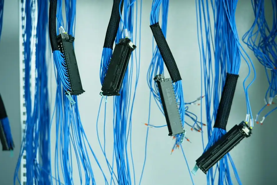
A 2oo3 (two-out-of-three) voting logic solver remains the textbook configuration for SIL3 safety instrumented functions (SIFs) in process plants, because it tolerates one failed channel without compromising the safety action and without immediately causing a spurious trip [S4].
For process industries with low demand rates, the architecture is selected specifically to minimise Probability of Failure on Demand (PFD), where a single-channel undetected failure would be unacceptable; a well-voted triplet keeps the dangerous failure rate bounded while still allowing degraded operation [S1].
What 2oo3 voting actually does inside a safety PLC
Inside a C Series functional-safety module, the module FPGA runs a two-step voting process before returning a current region to the user program, so the host application never sees an intermediate, half-decided state from a single diverging channel [S2].
The SIF itself is conventionally split into three sub-systems: the sensing element, the logic solver, and the final element. A 2oo3 arrangement is positioned as the optimal configuration for each of those sub-systems, combining AND and OR logic so that any two agreeing channels can assert a trip while disagreement is treated as a detected fault [S4].
The vote is therefore not a software trick but a hardware-voted decision, which is what allows the system to claim compliance with IEC 61508/61511 SIL3 and to be cited in vendor literature as a certified logic solver, not a generic PLC with extra diagnostics [S4].
PFD, PFH, and FIT: choosing the right metric
For low-demand SIFs the relevant metric is PFDavg, expressed as a dimensionless probability in the 10⁻³ to 10⁻⁵ range for SIL1 to SIL3, not a failure rate per hour; FIT (failures in 10⁹ device-hours) only enters the picture when the same hardware is used in a high-demand or continuous mode, where PFH (probability of failure per hour) replaces PFD [S1][S4].
The two metrics are not interchangeable: PFD integrates dangerous undetected failures over the proof-test interval, typically 1 to 5 years, whereas PFH is the dangerous failure rate of the high-demand path. A 2oo3 voter improves PFD for low-demand service mainly by shortening the diagnostic test interval on each channel and by voting out a single divergent channel before it can mask a real demand [S4].
For the voter itself, IEC 61508/61511-compliant designs shown in published SIF simulations report the lowest component count and the lowest failure rate, with the highest mean time to failure, when the voting element is a passive device rather than a microcontroller [S4].
Where 2oo3 beats 1oo2 and 2oo4: a criteria comparison

Against the common alternatives, 2oo3 sits between 1oo1 (single channel, cheapest, worst PFD) and 1oo2 (two channels in series, best PFD, worst availability, since any one failure trips the process) [S1].
The decision axis is therefore not "more redundancy is better" but a trade between tolerable spurious-trip cost and tolerable PFD. Process units with high production loss per spurious trip, such as compressors and large reactors, gravitate to 2oo3 specifically because one failed channel does not force a plant trip; safety-critical units with severe overpressure consequence, such as gas wellhead HIPPS, also favour 2oo3 because two agreeing channels are enough to fire the ESD valve above the trip threshold [S3].
Reference implementation: 2oo3 HIPPS on a Moore SLA
A published HIPPS design for upstream gas wellheads uses three 0-10,000 psi smart HART pressure transmitters, a Moore Industries SLA multiloop logic solver in a 2oo3 voting architecture, an RTU/PLC for non-safety monitoring, and an emergency shutdown (ESD) valve as the final element [S3].
The SLA's trip setpoint is 8,700 psi on at least two of the three transmitters, which corresponds to roughly 87% of the 10,000 psi transmitter full scale and is below the rated wellhead pressure, giving margin for sensor drift between proof tests [S3].
Each of the SLA's three input channels carries an integrated loop power supply, so the three smart HART pressure transmitters are powered directly from the logic solver without an external power supply, and the HART signal is passed through to the corresponding analog outputs. This lets the RTU/PLC see every transmitter's PV, diagnostics, and HART variables without breaking the safety chain, while a read-only Modbus RTU link carries all internal equations, alarms, and relay status to the control system [S3].
The safety-relevant benefit is that the SLA's retransmission isolates the 2oo3 logic from the RTU/PLC's analog input cards: a catastrophic failure of the control system's I/O does not affect the independent 2oo3 shutdown path, which is the architectural reason this pattern is repeated across ESD, fire and gas, and HIPPS applications [S3].
FPGA voter, diagnostics, and Type A vs Type B components
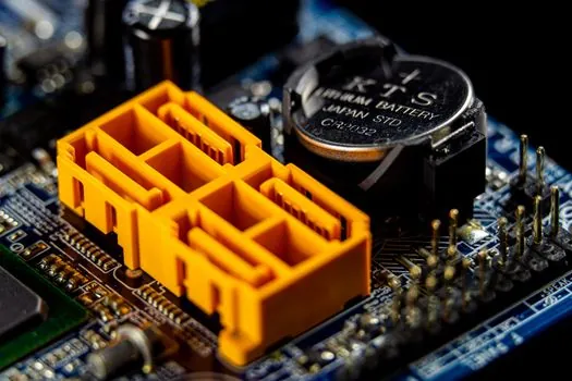
Inside NI C Series functional-safety modules, the vote is committed by the module FPGA in a two-step process, which means the host CPU is not in the safety-critical decision path and the safety function continues to operate even if the controller's user program stalls [S2].
At the component level, IEC 61508 partitions devices into Type A (simple, well-characterised, with defined failure modes, such as resistors, capacitors, inductors) and Type B (complex, with non-exhaustive failure modes, such as microcontrollers and ASICs). A 2oo3 logic solver built predominantly from Type A components is treated as more deterministic, and published simulations show a passive-voter realisation has the lowest component count, the lowest failure rate, and the highest mean time to failure of the compared voters [S4].
This is one of the reasons the memristor-based passive voter described in the ECSA-10 proceedings is positioned as a candidate replacement for the microcontroller-based voter: it keeps the Type A failure profile while adding memory of the previous safe state, which the paper's LTspice simulation validates against an IEC 61508/61511 SIL3 target [S4].
When 2oo3 is the wrong choice
2oo3 is not free. The voter triples the I/O count, the sensor cost, the calibration workload, and the proof-test hours per SIF, so for low-consequence service the extra hardware is hard to justify against 1oo1 or 1oo2 [S1].
It is also a poor fit for applications where the safety action must never be initiated by a single faulty channel but where losing one channel is acceptable; in those cases, a 1oo2 (vote-out) is cheaper and gives a better PFD because the two channels are diagnostically cross-checked in series [S1].
Finally, a 2oo3 architecture does not by itself reduce the dangerous undetected failure rate of each individual transmitter: the vote only catches disagreement after a channel has already failed dangerously. The PFD improvement comes from shorter diagnostic test intervals on each channel, not from the vote alone, and that is why published HIPPS designs still require periodic proof testing of all three transmitters and not just the logic solver [S3].
Sourcing and standards trail to verify
For any SIF design the verification trail should reference IEC 61508 (the umbrella functional-safety standard) and IEC 61511 (process-sector implementation), with a vendor SIL3 certificate that names the exact hardware and firmware revision; the FPGA-voted C Series module is documented as a two-step voter at the module level, and the SLA-based HIPPS design is published as a complete reference with 8,700 psi trip, 10,000 psi span, and Modbus RTU diagnostics [S2][S3][S4].
Next signals to watch: vendor updates to certificate scope covering HART pass-through, integration of memristor-based passive voters into commercial SIL3 logic solvers, and harmonisation of the FPGA-voted two-step process with the next revision of the IEC 61508/61511 voter-architecture examples [S2][S4].
For component-level specifications, see construction machinery and equipment, lamps and light fittings, and lighting equipment and electric lamps.
This topic is covered further in Aerial Work Platform Safety: Standards, Tilt Limits, and Operator Pre-Shift Rules.