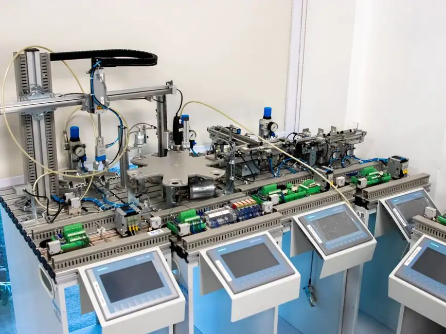
An off-board DC fast charger is built around a two-stage power conversion chain: a grid-facing AC/DC converter followed by an isolated DC/DC stage that drives the EV battery directly, with galvanic isolation between the AC supply and the DC output mandated by IEC 61851-23 [S2]. This topology defines the entire process-control problem, because every protection loop, every power-quality limit, and every charging profile is measured across those two stages.
The 100 kW Level 3 / Level 4 class is now the mainstream commercial target, designed to charge a 400 V or 800 V battery to 80% in under 30 minutes, and increasingly specified for both unidirectional and bidirectional (G2V/V2G) operation [S2]. With SiC semiconductors, modular power stages, and battery energy storage system (BESS) buffering to cut grid peak demand, the control problem has shifted from simple constant-current/constant-voltage (CC/CV) to a multi-loop, multi-timescale system [S2][S3].
Two-Stage Topology and Where the Control Loops Close
The AC/DC stage is typically a Vienna rectifier or a three-level active front end that meets grid harmonic and power-factor targets while feeding a regulated DC bus, and the downstream DC/DC stage (often a dual-active-bridge or resonant LLC) delivers the isolated, wide-output battery current [S2]. Each stage needs its own local current and voltage feedback, plus a station-level controller that runs the charging-state machine, the OCPP back-office link, and the thermal derating logic.
Galvanic isolation between AC and DC is mandatory under IEC 61851-23, which forces the DC/DC stage to use a transformer-isolated topology; this directly affects sensor placement, because current transformers or Hall-effect sensors must sit on the battery-side of the isolation barrier where the high-frequency switching common-mode noise is worst [S2]. Reliability-oriented reviews of DC fast chargers note that low-level control (current sharing between paralleled modules) and system-level control (power dispatch between grid, BESS, and EV) are explicitly separated to keep the inner loop bandwidth at the kHz range and the outer loop in the sub-Hz range [S3].
Sensor Selection: Current, Voltage, and Temperature as the Primary Feedback
Process control in a DC fast charger rests on three measurement families: DC bus current sensors (typically open-loop or closed-loop Hall-effect in the 0-1500 A range), DC voltage sensors on the high-voltage bus and the battery output (400 V and 800 V classes), and a temperature sensor network that includes IGBT/SiC module baseplate thermistors, coolant inlet/outlet RTDs or PTCs, and CCS cable temperature monitoring [S4].
Current sensors are exposed to the full DC fault current of the station, and voltage sensors must tolerate the DC bus transient overshoot during load steps and BESS mode transitions, so a typical spec window is roughly 50-1000 A for current and 0-1000 V DC for voltage on a 400 V system, scaled to 0-2000 V DC on an 800 V architecture [S4]. The same measurement chain also feeds the DC energy meter (kWh billing) mandated in many jurisdictions, so accuracy, linearity, and isolation voltage are competing constraints; integrated Hall sensors with built-in isolation are increasingly preferred over shunt resistors for the high-current battery loop, because they eliminate the high-power dissipation and thermal drift of a precision shunt [S4].
Level 3 vs Level 4: 100 kW and Beyond, Compared on Decision Criteria
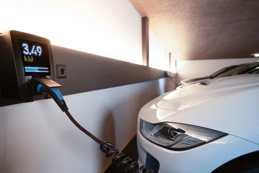
Three decision criteria separate the main options a specifier will see in 2026: output power class, battery voltage support, and bidirectional capability. Level 1 (≤ 19.2 kW) and Level 2 (≤ 43 kW) are AC on-board chargers, not relevant here, while the DC fast-charging space is split into Level 3 (typically 50-150 kW) and Level 4 (≥ 150 kW, often 350-400 kW for HPC stations) [S2].
On power density and efficiency, SiC-based 100 kW modules now sit around 97% peak efficiency with power densities in the 3-5 kW/L range, and they natively support both 400 V and 800 V battery packs without a separate boost stage, which simplifies the DC/DC control loop [S2]. Liquid-cooled Level 4 chargers push higher (350-400 kW) by paralleling more SiC power modules and using a higher DC bus voltage (often 800 V nominal), at the cost of a much more aggressive thermal envelope and stricter isolation coordination on the CCS cable [S2][S3].
BESS-Buffered Stations and the Resulting Control Stack
DC fast chargers paired with a stationary battery energy storage system introduce a second, slower control layer that decouples the grid draw from the EV charge profile, so the inner converter loop can follow the EV demand while the outer loop shapes the grid power [S3]. A typical architecture uses a bidirectional DC/DC between the BESS and the charger DC bus, with a supervisory controller that schedules the BESS state-of-charge, enforces grid import limits, and arbitrates between simultaneous EV sessions on a multi-dispenser site.
Reliability-oriented reviews of these systems emphasise prognostic health monitoring for the BESS (cell-level voltage and temperature drift tracking) and for the power electronics (thermal cycling, switching stress, and DC-link capacitor ESR trending) as the main levers to push Mean Time Between Failures into the 50,000-100,000 hour range typical of utility-grade converters [S3]. Cooling is a direct control variable, not just a thermal afterthought: liquid cooling of the SiC modules keeps the junction-to-case delta within roughly 40-60 C under full load, which is the operating window where vendor-accelerated life data remains valid [S3].
Standards, Compliance, and What the Process-Control Loop Must Enforce
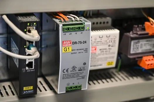
The functional-safety and process-control boundaries are set by a small set of standards that any serious spec should call out. IEC 61851-23 governs the DC charging system itself, including the isolation requirement between AC and DC and the digital communication over the CCS PLC channel; ISO 15118 defines the high-level charging protocol including Plug & Charge, and OCPP 2.0.1 covers the back-office link used for load management and billing. [S2]
Power-quality and grid-side compliance are normally verified against IEEE 519 (harmonic current limits) and regional grid codes (e.g. the German VDE-AR-N 4105 for low-voltage interconnection, or the EN 50549 family in Europe), while the BESS sub-system falls under UL 9540 / IEC 62933 for energy storage system safety and UL 1973 for the cell-level qualification. Inside the converter, IEC 62477-2 covers the power electronic converter safety, which interacts with the sensor and protection design by setting the clearance, creepage, and impulse-withstand values that the Hall-effect current sensor isolation must meet [S2][S3].
Who DC Fast Charger Process Control Is For, and Where It Stops Being Useful
This instrumentation and control architecture is for high-power public and fleet DC fast charging sites where charging session throughput, grid-friendly operation, and remote diagnostics all matter at once. It is not a sensible fit for slow AC workplace charging (Level 2 at 11-22 kW) or for residential boxes, where the converter stage, the isolation barrier, and the sensor accuracy budget all collapse into a much simpler CC/CV brick. [S2]
The architecture is also a poor match for ultra-lightweight, cost-engineered urban DC wall boxes in the 25-50 kW range, where the BESS buffer, the bidirectional V2G, and the liquid cooling are normally stripped out to hit price targets, and the process control reverts to a single-loop CC/CV with a basic Hall sensor and a thermistor on the heatsink [S2][S4].
Failure Modes and Constraints Specifiers Should Track
The most common failure modes flagged in reliability reviews are DC-link capacitor degradation (capacitance loss and ESR rise under thermal cycling), IGBT/SiC bond-wire fatigue under high di/dt, and BESS cell drift under partial state-of-charge cycling typical of buffered fast chargers [S3]. Each of these has a measurable signature on the existing sensor suite: capacitor degradation shows up as increased DC bus voltage ripple at a fixed load step, bond-wire fatigue shows up as an increasing on-state voltage drop (Vce(sat) or Vds(on) rise) at a fixed current, and BESS drift shows up as cell-voltage spread under a constant load.
The other hard constraints are the CCS cable thermal limit (which forces a derating curve from the controller above roughly 200-250 kW per cable for uncooled Type 1/Type 2, and higher with liquid-cooled cables) and the grid connection limit (which is why a BESS buffer is so often added for stations above 150-200 kW of simultaneous output) [S2][S3]. For an engineer sizing a new site, the next data node worth tracking is the DC fast charger manufacturing quality benchmarks that drive the realistic availability number, and the underlying dc power supply topology choices that determine sensor bandwidth and isolation margins.
The underlying component specifications are covered under process control, and dc dc converter.