
A 4-20 mA gas detector, like any NE43-compliant smart transmitter, uses 4 mA as live zero and 20 mA as 100% of range, then drives outside that band in two defined ways: a saturation overrange at 20.5 mA, and a hardware fault at 21.0 mA (upscale) or 3.6 mA (downscale) [S4].
The system consists of a DC power supply, the 2-wire or 4-wire gas transmitter, the analog input card or controller, and series wiring; total loop voltage drop must leave enough compliance headroom for the transmitter to regulate 20 mA at maximum [S5]. For gas-detection practice the same NE43 thresholds apply whether the measured variable is ppm of H2S, LEL percent, or oxygen percent volume.
Why gas-detection loops need a fault band separate from overrange
The 4 mA live zero was deliberately chosen so that 0 mA unambiguously means a broken wire, a dead transmitter, or a missing power supply, not a real zero concentration reading [S5]. NE43 extends that logic upward: a current that climbs to 21.0 mA tells the controller that the sensor element, A/D converter, or microprocessor has self-diagnosed a fault, not that the gas concentration is merely above range [S4]. The 0.5 mA gap between the 20.5 mA saturation ceiling and the 21.0 mA fault level is intentional deadband the control system should not interpret as a valid measurement; values falling in 3.6-3.8 mA and 20.5-21.0 mA are reserved as "should not occur" bands under the NE43 definition [S4].
For gas detection in particular, distinguishing "over-range exposure event" from "sensor head failed" is a safety question, not a display question, because the same upstream PLC branch often drives ventilation starters, ESD-1 trips, and personnel alarms. Conflating the two has historically driven mis-specs in fixed gas detectors for combustible-gas LEL where overrange can approach 100% LEL or even 100% v/v methane during a pipeline purge.
NE43 current band table: saturation vs fault
Working from the NE43 signal-level diagram [S4], the bands applied to a combustible-gas or toxic-gas transmitter current output are:
3.0-3.6 mA: below the downscale fault level, reserved for the transmitter's own loop-power housekeeping, not a valid measurement. 3.6 mA: downscale hardware fault, set by the device microprocessor when self-diagnostics fail. 3.8-4.0 mA: low saturation, the bottom of the overrange band reached on a normal under-range condition (for example, a negative reading from a sensor that has drifted past zero). 4.0-20.0 mA: valid measurement range, exactly 0-100% of the calibrated full scale. 20.0-20.5 mA: high saturation, top of the overrange band; the controller should interpret as "concentration above full scale, sensor still healthy". 20.5-21.0 mA: white gap, invalid region, should never appear in a properly functioning system. 21.0 mA: upscale hardware fault, the gas transmitter's fail-safe output when the device has failed self-test. Above 21.0 mA, up to roughly 22-23 mA: the controller input range ceiling, useful for distinguishing a true 21 mA fault drive from a wiring short that lifts the loop to compliance [S4].
For toxic-gas transmitters (H2S, CO, NH3) the same numbers apply because NE43 is defined on the loop, not on the gas species; the configured 4 mA and 20 mA engineering values change (e.g., 0-50 ppm H2S, 0-25% LEL methane), but the saturation and fault thresholds are fixed at 3.8 / 20.5 mA and 3.6 / 21.0 mA respectively [S4].
Upscale vs downscale: which side to pick for gas loops

For 2-wire loop-powered gas detectors, the recommendation in NE43 commentary is to set the hardware fault output upscale to 21.0 mA, because the gas detector itself is already drawing the loop current for its own operation and may not be able to regulate a clean 3.6 mA downscale drive [S4]. For 4-wire gas detectors with a separate mains supply to the transmitter, either 3.6 mA or 21.0 mA is technically valid because the device no longer depends on the 4 mA minimum to power its own electronics [S4].
For personnel-safety combustible-gas detection, the practical consensus is upscale: a 21.0 mA fault signal forces a trip-style response in the controller (normally configured as "fail-safe = alarm") instead of allowing a 3.6 mA signal to be misread by an old analog input card that is still scaled to 4-20 mA. For oxygen enrichment or depletion detection on confined-space entry, upscale is again preferred because an "under-range at 0% O2" condition is itself a hazard, and driving the loop to 21.0 mA for a fault avoids a fault being confused with a real low-oxygen reading.
Common overrange and fault patterns engineers actually see in the field
A reading pinned just above 20 mA but below 20.5 mA typically means the gas concentration is genuinely above the configured full scale, not a sensor failure, and the appropriate response is calibration range re-check or sensor replacement on lifecycle, not a transmitter swap [S4]. A reading pinned at exactly 21.0 mA (within the controller's input tolerance) almost always means the transmitter's self-diagnostics have detected an internal fault, most often a poisoned combustible sensor, a depleted electrolyte in an electrochemical toxic sensor, or a failed IR source in a point IR detector [S3][S4].
A current in the 3.6-3.8 mA white-gap region means either an installer error, a misconfigured failsafe direction, or a transmitter that is non-NE43 compliant and is using the band illegally [S4]. A current that climbs past 21 mA and into the 22-30 mA region, as discussed in instrumentation forums, is most often a wiring short on the field side that lets the power supply push current beyond the transmitter's regulating range; the loop voltage drop collapses and the current rises until limited by the supply or wiring resistance [S2]. The original Control Global column also notes that some process loops see output current plateau somewhere in the 17-19 mA range when the transmitter cannot reach its commanded output, typically because the loop supply voltage minus the total loop IR drop has fallen below the transmitter's minimum compliance voltage at 20 mA [S1].
Selection checklist: what to verify on the gas transmitter datasheet
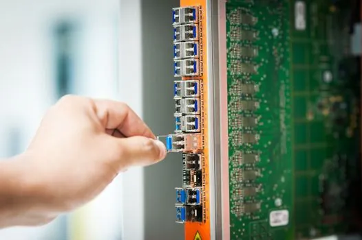
When specifying a fixed gas detector for a Safety Instrumented Function (SIF), the following NE43-related items should be confirmed in writing from the vendor before purchase: [S3]
1. Compliance statement to NAMUR NE43 with the saturation levels (3.8 mA low, 20.5 mA high) and fault levels (3.6 mA downscale, 21.0 mA upscale) published in the datasheet. 2. Selectable failsafe direction (upscale/downscale) in the device configuration tool, and the factory default. 3. Minimum loop voltage at 20 mA, typically 10-12 V DC for 2-wire electrochemical and 16-18 V DC for 2-wire catalytic-bead or NDIR combustible sensors; this is the compliance headroom the installer must budget against the 24 V DC supply and the cabling resistance at maximum cable length. 4. Maximum loop current under fault, normally clamped near 22-23 mA so that the controller input can be ranged 0-22 mA to discriminate "true 21 mA fault" from "shorted loop at 30 mA" [S4]. 5. Diagnostic coverage and what fault conditions actually drive the 21.0 mA output, since not all "faults" are equal to the SIF proof-test interval. 6. Behavior on sensor end-of-life, since for oxygen and several toxic-gas sensors the end-of-life signal is configured as a special current in the 3.6-3.8 mA band, and the controller must be configured to interpret that band correctly rather than treating it as a generic downscale fault.
Receiver setup: the controller side of the 4-20 mA gas loop
NE43 is only useful if the receiving analog input module is ranged at least 0-22 mA and the controller logic interprets the overrange and fault bands as distinct states, not as clamped readings at 0% or 100% [S4]. A common engineering mistake is leaving the input card at its default 4-20 mA range with burnout detection set only to "low" (3.6 mA), which silently maps a 21.0 mA upscale gas-detector fault into a clamped 100% LEL reading, exactly the wrong direction for safety [S3][S4]. The correct setup is a separate "fault" alarm mapped to the 3.6 mA and 21.0 mA bands, independent of the overrange alarm mapped to 20.5 mA, and a separate "sensor end-of-life" alarm mapped to whatever band the vendor uses for that specific diagnostic.
For SIS design, a useful reference is the comparison of single-sensor trip against 2oo3 voting in 2oo3 voting logic for gas detection; NE43 fault signaling only delivers its safety value when the voting and input-range logic downstream are also designed to consume those bands as distinct states.
Troubleshooting field symptoms on a gas loop

Reading between 3.6 and 3.8 mA on a toxic-gas channel: confirm the failsafe direction in the transmitter config; if set upscale, this is a wiring or install error; if set downscale, this is a legitimate fault and the sensor head should be inspected [S4]. Reading at exactly 21.0 mA on a combustible-gas channel: bench-test the sensor head on the manufacturer bump-gas; if the head responds, the transmitter electronics are flagging an internal diagnostic and the head should be replaced; if the head does not respond and the current stays at 21.0 mA, the transmitter module itself has failed [S3]. Reading at 30 mA or higher with the loop voltage collapsed: open the field junction box and look for a pinched cable against conduit, water in the cable gland, or a shorted termination in the detector head; this is almost never a transmitter electronics fault [S2]. Reading plateaued at 17-19 mA on a high-concentration event: measure the loop voltage at the transmitter terminals under the alarm condition; if it has dropped below the transmitter's stated minimum compliance at 20 mA, the cabling is too long for the 24 V supply and a higher-voltage supply or a heavier-gauge cable is the fix, not a transmitter swap [S1].
For a broader view of how instrument loop health ties into the wider industrial equipment stack, the construction-machinery-side discussion of pressure-loop loading and pneumatic-control history in differential-pressure-transmitter selection covers the same compliance-budget logic applied to flow and level loops, where the 4-20 mA current band must be preserved end-to-end.
Bottom line: on a 4-20 mA fixed gas detector, expect 4.0-20.0 mA for normal measurement, 3.8-3.6 mA and 20.5-21.0 mA as named saturation and fault bands, the 0.5 mA white gaps in between as invalid by definition, and any reading outside 3.0-22.0 mA as a loop-wiring problem rather than a sensor or transmitter problem. The two trackable signals to watch over the next revision cycle are: (1) whether SIS-vendor analog input cards ship with 0-22 mA ranging and named NE43 fault alarms enabled by default, and (2) whether catalytic-bead and NDIR combustible sensor manufacturers publish explicit sensor end-of-life current bands in the 3.6-3.8 mA region so that operators can distinguish EOL from generic downscale fault without a HART interrogation.
Component reference pages worth checking: eddy current tester, and checking and testing apparatus.