Additive manufacturing (AM) builds parts by joining material layer-by-layer from 3D model data, producing far less waste than subtractive milling while trading throughput for geometric freedom [S5]. Engineers in 2026 are choosing between seven ISO/ASTM 52900 process families — material extrusion, VAT photopolymerisation, powder bed fusion (PBF), directed energy deposition (DED), material jetting, binder jetting, and sheet lamination — based on material, tolerance, lot size, and required post-processing [S5].
The market for AM simulation software, which validates distortion and residual stress before a build is started, has consolidated around suites spanning design, process simulation, and final-part verification [S1]. For reference on how this layer-by-layer approach compares to other discrete build methods, see the industrial robot manufacturing process map.
Seven Process Families: Where Each One Wins
ISO/ASTM 52900 partitions AM into seven families, each with a distinct energy source, feedstock state, and resolution envelope [S5]. Powder bed fusion (PBF) — including selective laser melting (SLM) and electron beam melting (EBM) — uses a thermal source to fuse metal powder layers 20–100 µm thick, achieving densities above 99% in titanium, Inconel, and 316L stainless when process parameters are controlled [S5]. Directed energy deposition (DED) feeds powder or wire into a moving melt pool created by a laser or plasma arc, suiting large titanium and nickel-alloy repairs and hybrid additive-subtractive cells [S1].
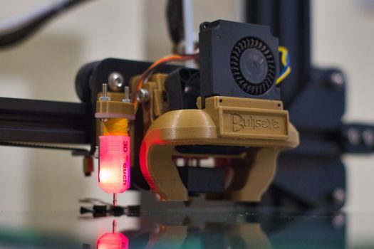
Material extrusion (FDM/FFF) deposits thermoplastic filament through a heated nozzle, typically at 50–400 µm layer thickness with dimensional accuracy around ±0.2% [S5]. VAT photopolymerisation (SLA, DLP) cures liquid resin with UV light, hitting ±0.1 mm tolerances on parts below 600 mm and wall thicknesses below 0.5 mm [S5].
Material jetting dispenses photopolymer droplets that are UV-cured, offering multi-material and high surface finish (up to 16 µm Ra) but with a narrow material library. Sheet lamination bonds and cuts sheets of metal or composite foil, used for low-cost metal prototypes and multi-material layups. A direct line-by-line comparison appears later in this article.
Selection Criteria: Material, Tolerance, Volume, Post-Processing
The first gate is feedstock compatibility: polymers, metals, ceramics, composites, and sand each map to a different process subset [S5]. The second gate is geometric tolerance: PBF metal delivers ±0.1–0.2 mm at 30–80 µm layers; FDM delivers ±0.2% with a 0.4 mm nozzle; SLA hits ±0.1 mm but caps part size around 600 mm on most platforms [S5]. The third gate is lot size: binder jetting of metal and PBF with multi-laser build envelopes (≥400 × 400 × 400 mm) are the only AM routes that compete with CNC on production runs above 1,000 parts [S5][S1].
The fourth, often-overlooked gate is post-processing burden: PBF metal requires support removal, stress relief, hot isostatic pressing (HIP) for fatigue-critical parts, and machining of mating surfaces. DED parts require near-net machining of every functional surface. Manual processing time and powder exposure are explicit evaluation criteria in published AM automation-potential studies — manual time per build and operator exposure to powder being scored separately from theoretical automation potential [S9]. For more on how discrete manufacturing cells plan post-processing flow, see the semiconductor manufacturing process flow.
Simulation, In-Process Monitoring, and Defect Detection
AM simulation is no longer optional for regulated parts: it predicts thermal distortion, residual stress, and support-structure failure before powder is melted [S1]. Commercial suites now span the full workflow — design for AM, print-process simulation (covering PBF, DED, and metal sintering workbenches), and final-part structural verification [S1]. Engineers at large chemical companies run these simulations in parallel with physical builds to cut qualification time on metal serial parts [S8].
Defect detection uses optical tomography, melt-pool thermography, and — increasingly — deep-learning image segmentation trained on labelled layer images [S4]. Convolutional and U-Net architectures applied to in-situ layer images reach above 90% classification accuracy on lack-of-fusion and keyhole-porosity defects in published PBF studies, though the exact number varies with dataset and alloy [S4]. For background on the broader machine-learning pipeline, see the additive manufacturing material encyclopedia entry.
Multi-Material, Hybrid, and Multi-Laser Builds
Multi-material AM is one of the most active 2026 development areas: process chains that combine a hard steel working surface with a copper-alloy cooling channel inside a single build are in serial production at bearing and forming-tool makers [S10]. The technical challenge is interface metallurgy — the bond zone between two alloys must avoid brittle intermetallics, which is why process windows for multi-material DED are typically narrower than single-alloy DED [S10].
Multi-laser PBF systems with 4 to 12 lasers operating in a single build chamber raise throughput to 80–120 cm³/h on 316L stainless and titanium Ti-6Al-4V, but introduce overlap-zone control problems. A full-process automation assessment ranks number of process decisions, manual activities, and investment cost as the highest-weight evaluation criteria for AM cells [S9]. For complementary coverage of multi-cell integration, see the robotics smart manufacturing 2026 integrator spec gates.
Comparison Table: Seven Families on Four Decision Gates
The table below condenses the four decision criteria — typical tolerance, material coverage, lot-size band, and dominant post-processing burden — for the seven ISO/ASTM 52900 families [S5].
Material extrusion (FDM/FFF): tolerance ±0.2% (lower bound ~±0.1 mm); materials thermoplastics (ABS, PLA, PA12, PEEK); lot size prototype to short-run; post-processing support removal, light sanding [S5].
VAT photopolymerisation (SLA/DLP): tolerance ±0.1 mm; materials UV-curable resins (standard, tough, castable, dental); lot size prototype and small series; post-processing UV post-cure, support removal [S5].
Powder bed fusion (PBF metal/polymer): tolerance ±0.1–0.2 mm; materials metals (316L, Ti-6Al-4V, Inconel 718, AlSi10Mg) and polymers (PA12, PA11); lot size serial production capable; post-processing stress relief, HIP, support removal, surface machining [S5][S1].
Directed energy deposition (DED): tolerance ±0.5–1.0 mm near-net; materials metals (titanium, nickel, cobalt-chrome, wire-feed steels); lot size repair, hybrid, large structural; post-processing heavy machining, HIP, stress relief [S1][S10].
Material jetting: tolerance ±0.02–0.05 mm; materials photopolymers, wax; lot size prototyping, medical models, casting patterns; post-processing UV cure, support removal [S5].
Sheet lamination: tolerance ±0.1–0.2 mm; materials paper, polymer, metal foil, composites; lot size prototype, low-cost tooling; post-processing edge finishing, machining [S5].
Failure Modes and Quality Limits Engineers Hit in Production
The three most common PBF defects are lack-of-fusion porosity (energy density below the bonding threshold), keyhole porosity (energy density above the vaporisation threshold), and balling (melt-pool instability from oxidation or scan strategy) [S4]. Each is detectable in-process with melt-pool monitoring cameras and post-process with CT scanning, but not every defect is repairable — lack-of-fusion in a fatigue-loaded aerospace part is a scrap event. Standards around this are still being formalised: ISO/ASTM 52900 covers process classification, and ISO/ASTM 52911 covers PBF design guidelines, but no single standard yet prescribes acceptance criteria for every alloy [S5].
DED parts suffer anisotropic tensile properties: as-deposited vertical coupons in Ti-6Al-4V can show elongation 30–50% lower than wrought baseline. HIP at 920 °C / 100 MPa / 4 h closes most of the gap but adds 8–12 hours of cycle time and roughly 20–30% to part cost. The point is that AM mechanical properties are not isotropic by default, and any spec sheet that quotes a single ultimate tensile strength is hiding direction-dependent data.
Standards, Sourcing, and 2026 Process Signals
Process naming and category classification sit in ISO/ASTM 52900; design guidelines in ISO/ASTM 52911 (PBF) and ISO/ASTM 52912 (DED); test methods in ISO/ASTM 52904 for metal PBF [S5]. Material-specific specs — ASTM F3055 for Ti-6Al-4V PBF, ASTM F3187 for 316L PBF, ASTM F3301 for AlSi10Mg PBF — give the as-built property envelope that procurement specs reference [S5].
Trackable signals through 2026: serial adoption of binder-jetted 4140 and 316L in automotive brackets; wider deployment of 12-laser PBF envelopes above 500 × 500 mm; growing use of multi-material DED for tooling inserts with conformal cooling. These three markers, plus the publication of new ISO/ASTM test methods, are the shortest path to gauge where the process map is heading next.
For component-level specifications, see multifunction process calibrator, and v process line.