Safety laser scanners on AGVs, AMRs, and industrial carts typically cover a 190–300° field of view in 2D, with the full 360° coverage achieved only by mounting three units at the front corners and rear of the vehicle, as implemented on AGILOX platforms at a scan plane of 80 mm above floor [S1][S2].
Operating protective fields for mobile robots most commonly fall in the 1.5–4.0 m range, while headline maximum protective field range typically sits between 3.0 m and 9.0 m depending on the optics class and reflective target used, with the actual field set well below the maximum so the safety function still holds at the worst-case response time [S3][S4][S6].
How the protective field is sized: it is not about max range
The protective field on a mobile robot is bounded by the safety chain's total response time, not the scanner's headline range: SICK's guidance is that a scanner with a 3 m controlled area permits a higher safe speed than a 1 m area because the vehicle has more distance in which to stop, and the maximum protective field is only one of several selection factors [S4].
A type 3 safety laser scanner conforming to EN 61496-1, with the AOPDDR requirements of IEC 61496-3, is limited to PLd under EN ISO 13849 or SIL2 under IEC 62061, and this performance level is what bounds the response-time budget the field-sizing math has to fit inside [S4]. For reference, a typical AGV travels 1.5–3.0 m/s in shared human spaces, which fixes a 1.5–2.0 m minimum protective field for a 1.5 m/s platform with sub-100 ms total safety response, and a 3.0 m/s platform needs roughly double that [S6].
Warning field vs protective field: the two-zone pattern
AGV-class safety laser scanners are configured with at least two distinct field sets: a warning field that triggers a speed reduction when an object is detected, and a protective field that triggers a full safety stop, with optional intermediate fields for speed-step behaviour as the vehicle approaches a line-side station [S3][S6].
Multi-field-set configuration lets the robot shrink its working zone in real time as line speed increases, which keeps the protective field as tight as the response time allows while preserving a wider detection envelope for slow or stationary states [S6]. A separate navigation laser scanner handles SLAM and contour matching, while the safety laser scanner is a discrete, type-approved device wired into the safety PLC; conflating the two is one of the most common integration errors seen in retrofits.
2D vs multi-layer 3D coverage: when 190° is not enough
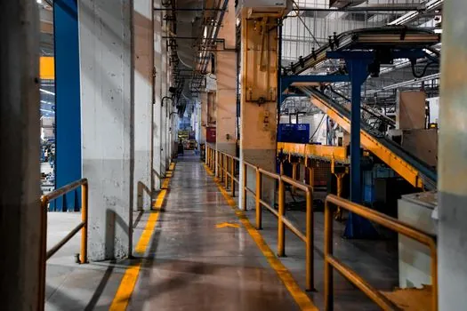
Area scanners for stationary robot cells monitor a 2D area at 190° with several metres of radius, while mobile platforms working around suspended loads, pallet overhangs, or human reach zones need multi-layer or 3D safety LiDAR to add vertical resolution to the protective field [S7].
The practical implication: a 2D scanner on an AGV only protects the scan plane (typically 150–300 mm off the floor), so a forklift fork-tip detector or a fork-height safety scanner is added when load geometry creates an overhead blind spot, and a separate safety laser scanner for pallet detection covers the rear approach [S2]. AGV designers should treat horizontal FOV, vertical layer count, and protective-field range as three independent selection axes, not a single "range" number.
Standards that govern the field: EN 61496, ISO 13849, ANSI/RIA 15.08
The standards chain that bounds scanner field sizing is: EN 61496-1 (electro-sensitive protective equipment, generic) and IEC 61496-3 (AOPDDR-specific) for the device, EN ISO 13849-1 for the PLd performance level, and IEC 62061 for SIL2, with ANSI/RIA 15.08 Part 1 in the US setting the system-level requirements for industrial mobile robots that the scanner field is then designed to satisfy [S3][S4].
AGV safety code sets a typical maximum operating speed of 2 m/s, and the "safe speed" for any given vehicle is derived from the time between detection and full stop rather than a fixed regulatory number, which is why the scanner field, braking system, and safety PLC response time must be specified together [S3]. Designers carrying out a full comprehensive risk assessment per EN ISO 12100 should size the protective field so the vehicle, at its top sustainable speed, can reach a safe stop before the farthest edge of the protective field.
Comparison: how 190° / 270° / 360° scanner setups differ
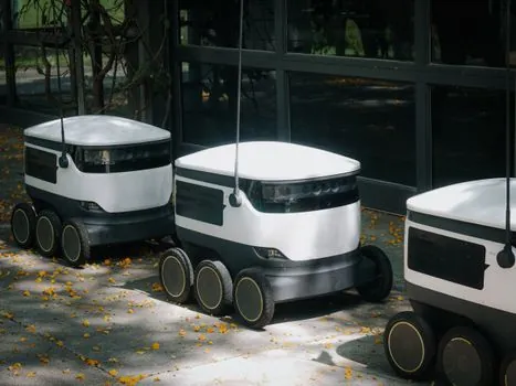
For a designer picking between configurations on a single AGV, the trade is straightforward: a single 270° scanner covers front and both sides in one device, which is the lowest-cost 2D option for a counterclockwise-only warehouse loop; two 270° scanners mounted back-to-back give full 360° with one redundant zone, which suits bidirectional traffic; and three scanners at the front corners plus rear centre give 360° with a 80 mm scan plane height and full per-corner overlap, the configuration AGILOX uses to eliminate blind spots at the chassis corners [S1][S2][S7].
On selection criteria, the comparison lands as: horizontal FOV (190° / 270° / 360°), protective field range (1.5–4.0 m typical, 3.0–9.0 m maximum depending on optics), safety rating (PLd / SIL2 per EN ISO 13849 and IEC 62061), and number of configurable field sets (warning + protective, often up to 4–8 settable zones for multi-speed behaviour) [S1][S3][S4][S6]. For 2D scanners, angular resolution (typically 0.1–0.5°) and scan cycle time (20–80 ms) are the next-tier criteria that drive whether a 30 mm obstacle leg can be detected at the far edge of the protective field.
Limitations and failure modes to spec in
Two failure modes dominate real-world AGV safety-laser deployments: (1) the protective field is sized to the scanner's headline range instead of the vehicle's actual stop distance, so at top speed the chassis overruns the field edge, and (2) the scan plane is set too high, so a low obstacle or a human foot is missed below the laser curtain [S4].
For pallet-handling and overhead-load cells, 2D coverage is insufficient and a multi-layer 3D safety LiDAR is the correct upgrade path [S7].
Selection workflow and what to track next
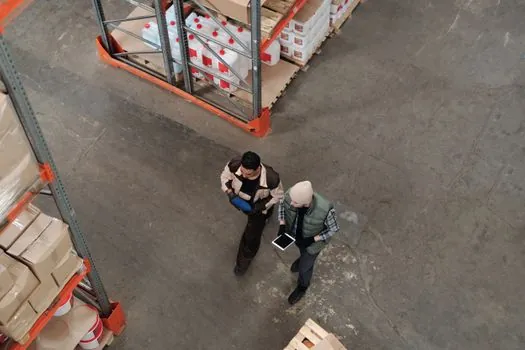
A spec-anchored selection starts with three numbers: top sustainable speed, total safety-chain response time, and required PL/SIL, then sets the protective field at braking distance plus a safety margin, not at the scanner's maximum range, then picks FOV from the chassis geometry, then confirms IEC 61496-3 and EN ISO 13849 certification, and only then looks at vendor-specific options [S3][S4]. For deeper context on how a SIL2/PLd safety chain is built around the scanner, the 2oo3 voting in SIL3 safety PLCs spec map walks the PFD-versus-FIT budget that the scanner's diagnostic coverage has to fit inside.
Trackable signals for the next quarter: any revision activity around IEC 61496-3 or EN ISO 13849-1 that shifts the PLd diagnostic-coverage threshold, broader adoption of 3D multi-layer safety LiDAR on AMR fleets operating around pallet racks and human reach zones, and growing overlap with the aerial work platform tilt and operator safety spec map as more shared-space mobile platforms enter mixed-fleet sites. Related category background lives in the AGV robot encyclopedia entry, and complementary obstacle-detection methods in the laser profiler reference.
For component-level specifications, see gas detection.