For hydraulic power units, the choice between an air-cooled fin-and-tube cooler and a water-cooled shell-and-tube or brazed-plate heat exchanger is set by four variables: available heat-rejection medium, ambient temperature, continuous heat load, and the cost ceiling for supporting infrastructure [S2][S3].
Air-cooled units use forced convection across aluminum or copper-brass fins, with fans ranging from small DC units drawing up to 40 A in extreme-duty mobile service to high-horsepower AC motors in industrial skids [S5]. Water-cooled units (shell-and-tube, brazed plate) use plant water, cooling-tower water, or a closed-loop chilled water circuit, and they transfer heat between two liquids at rates exponentially higher than a liquid-to-air surface can achieve [S4][S5].
Cooling Principles and Core Design
Air-cooled hydraulic oil coolers route hot oil through a finned aluminum or copper-brass core while a fan drives ambient air across the fin surface; common core constructions are tube-and-fin and bar-and-plate, with the bar-and-plate style using thick rectangular aluminum channels separated by aluminum fins to add internal turbulence at the cost of higher pressure drop [S2][S5]. The simplest tube-and-fin coolers are economically built from a snaked copper tube wrapped in aluminum or copper fins, light enough to bolt to the back of an electric motor and ride on the motor's own cooling fan [S5].
Water-cooled hydraulic oil coolers isolate the oil and water streams in separate channels, with shell-and-tube and brazed plate being the two dominant geometries; because water's specific heat and density exceed air's, a water-side cooler can reject a given heat load inside a noticeably smaller envelope, which is the reason water-cooled units are often preferred for high-load hydraulic systems, cramped machine rooms, and sites where ambient air runs hot [S2][S4]. Both core types depend on a clean water supply: without filtration, water treatment, and periodic descaling, the heat-transfer coefficient degrades and the cooler's nameplate capacity becomes aspirational [S2].
Air-Cooled vs Water-Cooled: A Criteria-by-Criteria Comparison
Upfront capital: air-cooled hydraulic oil coolers are consistently described as the lower-cost entry option, requiring only the cooler, the hydraulic hoses, and electrical power for the fan motor; water-cooled systems add the cooler plus pumps, supply and return piping, a cooling tower or chiller interface, and water-treatment hardware, and that infrastructure premium can be significant at the same nominal heat-rejection duty [S2][S3]. Installation footprint goes the other way: water-cooled units reach higher kW-per-cubic-foot because the heat-transfer coefficient on the water side is several times that of finned air surfaces, so a water-cooled cooler is usually smaller than an air-cooled cooler of equal duty [S2][S4].
Operating sensitivity: air-cooled capacity is gated by ambient air temperature and by fin cleanliness, so a hot-plant environment or a fouled fin pack can collapse derated capacity; water-cooled capacity is gated by water supply temperature, water quality, and the condition of internal tubes or plates [S2][S8]. Maintenance burden follows the same split: air-cooled coolers need clean fins and reliable fan motors, while water-cooled coolers need filtration, water treatment, and descaling to keep the heat-transfer surface from scaling over [S2][S8]. The article selection framework for hydraulic power units ties these variables back to the power unit's overall heat balance.
Capacity Ranges and Fan/Pump Sizing Reality
Standard catalog air-cooled hydraulic oil coolers span cooling capacities from a few kilowatts up to several hundred kilowatts, depending on core size, fan motor power, and fin density [S2]. For water-cooled shell-and-tube and brazed-plate units, API Heat Transfer markets the COLW (Cool Loop, Water Cooled) series as a shell-and-tube option and the BP series as a brazed-plate option, both sized for industrial hydraulic loops where plant water or a closed chilled-water loop is available [S4].
On the air side, mobile and severe-duty coolers frequently run DC fans that can pull 40 A or more in extreme mobile service, which is one reason hydraulic skid builders often switch to AC or hydraulically driven fans once the duty cycle and ambient climb together [S5]. On the water side, the open-loop river-water case can exploit a much larger delta-T than a closed chilled-water loop, because river water is colder than tower return unless a mechanical chiller is added, and that delta-T is what lets a water-to-water exchanger earn its higher capital cost back in steady-state heat rejection [S4]. The underlying physics of the plate heat exchanger geometry is what drives that delta-T advantage at compact size.
Use-Case Fit: Mobile, Industrial, and High-Load
Mobile machinery (ag tractors, construction equipment, refuse trucks, portable hydraulic tools) is the clearest air-cooled territory: no water utility, no plumbed return line, and the cooler often rides the structure or the reservoir itself; fin-and-tube with an AC, DC, or hydraulic-motor fan is the default [S2][S6]. Light-duty or low-horsepower hydraulic systems (small power packs, machine-tool hydraulics) also stay on air cooling because the heat load is modest and the basic tube-and-fin cooler is the most economical method available [S5].
Industrial fixed hydraulic systems in plants with a cooling tower, chiller, or river-water intake are the water-cooled use case: large hydraulic presses, plastic-injection clamp circuits, steel-mill hydraulic stations, and any installation where ambient air runs hot or floor space is tight [S2][S4]. When the heat balance pushes past the air-cooled envelope or when the plant already pays for a cooling-water loop, water-cooled shell-and-tube or brazed-plate is the engineered default, and the long-term efficiency of the liquid-to-liquid loop beats an oversized air-cooled bank in those service conditions [S2][S3][S4].
Limitations, Failure Modes, and Sourcing Constraints
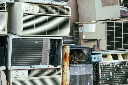
Air-cooled hydraulic oil coolers fail in three predictable ways: fouled fins that block airflow, failed fan motors (bearings, windings, drive belts on belt-driven units), and ambient-air temperatures that climb above design and erode capacity margin [S2][S8]. Water-cooled hydraulic oil coolers fail in their own triad: scaling and fouling on the water side, internal tube corrosion or plate erosion from aggressive water chemistry, and freeze damage in cold-climate installations where the water side is not drained or glycol-protected [S2][S4].
Specifying engineers should pin three numbers up front: the heat load in kW (or BTU/hr) to be rejected, the maximum allowable oil temperature at the cooler outlet (commonly 50 to 60 C for ISO VG 32/46 mineral oils, set by seal and oxidation limits), and the worst-case ambient air or supply-water temperature at the site [S2][S4][S5]. Without those three numbers the comparison is folklore, not engineering; the seller-side cost gap between air-cooled and water-cooled options widens fast once you add pumps, tower, and treatment skids to the water side [S2][S3]. Buyers tracking industrial lead times can cross-check the air-cooled chiller queue referenced in this 2026 CRAH/CRAC lead-time tracker since the same fan-and-fin supply chain feeds both markets.
Final decision rule of thumb for the spec sheet: choose air-cooled when the site has no water utility, the heat load sits comfortably under the catalog kW range, and ambient air stays below 35 to 40 C at design day; choose water-cooled when the heat load is high and continuous, the floor plan cannot absorb a large fin pack, and the plant already runs a cooling-water loop. Verify the cooler's nameplate capacity against the site's worst-case supply temperature (air or water), not the lab rating, and recheck that delta-T after every maintenance interval.
The underlying component specifications are covered under ballast water treatment.