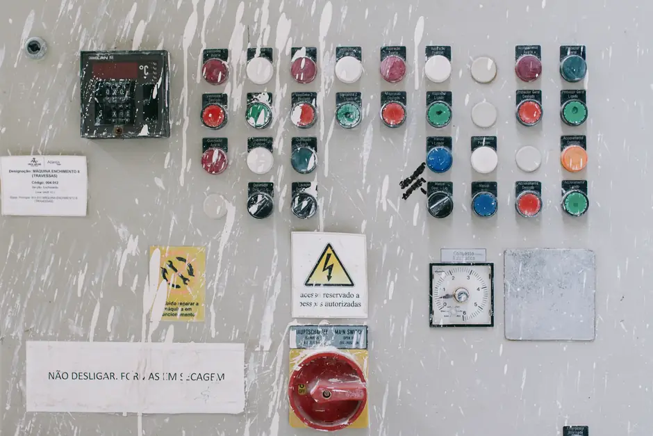
NFPA 79-2024 is the controlling U.S. electrical standard for emergency stop circuits on industrial machinery, while ANSI B11.0 (General Requirements and Risk Assessment) and ANSI B11.19 (Performance Criteria for Safeguarding) set the risk-based placement and performance rules for the same devices [S3][S5][S9].
Engineers building or retrofitting a machine in 2026 should treat NFPA 79 Chapter 10.5 as the authority for stop category, contactor selection, and control reliability, and ANSI B11.0 / B11.19 as the authority for whether an E-stop is even required, where it sits, and how it integrates with other safeguards [S3][S9].
What each standard actually owns
NFPA 79, "Electrical Standard for Industrial Machinery," owns the electrical implementation: stop categories 0, 1, and 2, contactor configuration, control-reliable logic, reset behavior, and the physical actuator requirements for the pushbutton (red actuator on a yellow background, self-latching, direct-opening contacts) [S2][S5][S8]. The 2024 edition added cybersecurity guidance for control systems and revised cable protection and wiring-method rules, but the E-stop core language carried over from the 2007 and 2012 harmonization with IEC 60204-1 [S5].
ANSI B11.0 and B11.19 own the risk-assessment and performance side. B11.0 defines how the risk assessment is performed, and B11.19 defines the performance criteria for the safeguarding devices that risk assessment selects; the E-stop is treated as complementary protective equipment under those documents, not as a primary safeguard [S2][S3][S9]. The B11.0 / B11.19 / NFPA 79 / Z244.1 integrated collection is sold as a single bundle by ANSI to keep these four documents aligned in one revision cycle [S1].
Stop categories 0, 1, and 2 per NFPA 79
NFPA 79 Chapter 10.5 is where the decision is made: every E-stop on a machine is assigned either Category 0, Category 1, or Category 2 based on the risk assessment, not by the controls vendor's default catalog offering [S3]. Category 0 is the equivalent of pulling the plug, an uncontrolled immediate removal of power to the machine actuators [S8]. Category 1 is a controlled stop where energy remains on the machine actuators long enough to stop motion safely, after which power is removed; the reset cannot restart motion on its own, a second deliberate action is required, such as a separate reset pushbutton or a twist/pull on the mushroom head [S2][S4].
Category 2 keeps power available to the actuators after the stop is achieved and is only used where a controlled continued energy state is needed (for example, holding a vertical axis against gravity during a controlled stop). Mis-applying Category 0 on a vertical-axis load, or Category 2 on a hazard that needs immediate de-energization, is one of the most common spec errors that show up in third-party safety audits [S3][S8].
Physical actuator requirements (red on yellow, mushroom, direct-opening)

NFPA 79 and IEC 60204-1 both require the E-stop actuator to be red, with a yellow background surrounding the mounting collar; the yellow field must extend at least 3 mm beyond the collar and remain visible around the actuator itself [S2][S4]. The pushbutton must be a self-latching palm or mushroom-head style with direct (positive) opening contacts, where the mechanical force of pushing the button physically breaks the contact weld-free [S2]. NFPA 79 does not permit flat switches, membrane switches, or graphical / digital representations of an E-stop on an HMI as the sole actuator, even though wireless and remote E-stops are permitted when they meet ISO 13850 and IEC 62745 [S4].
Resetting the actuator (twist, pull, or key-release) must not by itself restart hazardous motion; a separate deliberate action such as a dedicated reset pushbutton is required, and that reset action must be local to the operator station that initiated the stop [S2][S4]. Placement typically places E-stop devices at each operator control station and at additional locations around the machine or workcell, generally within 10 ft of any operator position [S2].
Risk assessment, placement, and the B11 side of the equation
ANSI B11.0 is the entry point: it tells the integrator how to perform the risk assessment that decides whether an E-stop is even required at a given station, and what Performance Level (PL) per ISO 13849-1 the stop circuit must achieve [S2][S3][S9]. ANSI B11.19 then defines the performance criteria for the safeguarding devices (including E-stops as complementary protective equipment) that the risk assessment selected [S2][S9]. The integrator documents severity, frequency of exposure, and possibility of avoidance, then maps that to a required Performance Level (a, b, c, d, or e), and only then turns to NFPA 79 for the electrical implementation that will actually deliver that PL [S3].
For routine build decisions, this means: B11.0 and B11.19 answer "do I need an E-stop here, and how reliable must it be?", while NFPA 79 answers "given that answer, which category, which contactor arrangement, and which reset sequence do I wire?". Treating NFPA 79 as the only document on a print is a frequent compliance gap, because the placement and risk-based reasoning still has to point back to the B11 series [S6][S9]. Engineers should also be aware that an emergency stop button selected for a Category 1 stop must carry direct-opening contacts rated for the full contactor coil current, not just for a logic-level signal, otherwise the positive-opening claim does not survive a contact weld.
Hardwired safety relay vs safety PLC vs PLC with safety bus
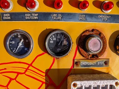
NFPA 79 has approved Safety PLCs and safety controllers for general industry since 2002, with integrated machine-drive safety systems added in the 2007 edition, so a hardwired dual-channel contactor arrangement, a dedicated safety relay, a safety PLC, or a standard PLC with a safety bus (PROFIsafe, CIP Safety) are all acceptable implementations when the chosen architecture meets the PL dictated by the B11.0 risk assessment [S3][S5]. The decision is not regulatory but engineering: hardwired is the cheapest path for a single E-stop on a simple machine, a safety relay is the common choice for one to four stop circuits with discrete I/O, and a safety PLC or safety-bus I/O is the right answer when the same controller is also handling light curtain, guard interlock, and E-stop signals with diagnostics.
For the E-stop circuit itself, NFPA 79's "the function of the E-Stop must be ensured" language pushes designers toward control-reliable logic, meaning a single contactor or a single wire failure cannot prevent the stop from working on the next demand [S5]. A typical control-reliable arrangement uses two contactors in series with mechanically linked or mirror-contact auxiliaries, each monitored by a safety relay or safety-PLC input, with the E-stop pushbutton breaking both coils through its direct-opening contacts. Wireless and remote E-stops, which the same standards permit, are most often justified on crane and AGV applications where the operator moves around the hazard zone and the cost of a trailing cable is prohibitive [S4].
Cross-references that bite at audit time
NFPA 79 and ANSI B11 do not live in isolation: NFPA 79 makes informational references to the ANSI B11 series, while OSHA's general-duty clause (29 CFR 1910.212) is the U.S. enforcement hook that points inspectors at both documents during a machine-related incident [S3][S6]. ISO 13850 is the international twin of the NFPA 79 E-stop rules and is the document that drives harmonized designs for global machinery builders, while IEC 60204-1 is the electrical-equipment twin that NFPA 79 has tracked since the 1997 edition [S2][S5]. For U.S. domestic builds, the practical hierarchy is: ANSI B11.0 for risk assessment, ANSI B11.19 for safeguarding performance criteria, NFPA 79 for the E-stop electrical implementation, with ISO 13850 and IEC 60204-1 cited as the harmonized basis for any deviation.
Two recurring audit findings on this stack: (1) flat or membrane-style E-stops used in place of a red mushroom pushbutton, which fails NFPA 79 and ISO 13850 simultaneously, and (2) a single contactor with no monitored mirror contact, which fails the control-reliable read of NFPA 79 even though the circuit will "work" on the bench [S4][S5]. The emergency stop device itself only carries part of the compliance load, the contactor arrangement and the reset logic carry the rest. Specifying engineers building any new U.S. For complementary machine-area lighting decisions that often sit on the same E-stop drawing (stops at aisle egress, illuminated status beacons), a machine-area emergency light spec should be reviewed against NFPA 101 life-safety rules separately from the NFPA 79 electrical-side E-stop circuit.
This topic is covered further in Stainless Steel in the Watch Market: Material Specification, Consumer Positioning, and....