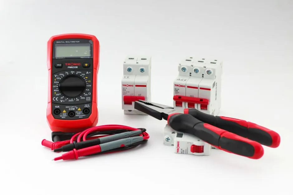
Automatic level maintenance in an electrical installation is not a single instrument, it is a regime of scheduled inspection, thermography, insulation testing, and de-energized cleaning that targets failure modes before they trip a breaker. Hartford Steam Boiler EPM guidance states that more than two-thirds of electrical system failures are preventable with a routine preventive program, and that the failure rate of equipment not on a scheduled plan runs three times higher than equipment that is [S5].
The scope covers switchgear, transformers, busways, protective devices, and the wiring environment itself, governed by the Electricity at Work Regulations 1989 (UK), BS 7671:2018+A1:2020 (IET Wiring Regulations), EN 50110-1 for operation of electrical installations in the EU, and NFPA 70E in the US [S2][S4]. Maintenance windows are typically set at three-year intervals as a baseline, with harsher or mission-critical loops shortened to 6-12 months [S5].
Scheduled Tasks and Test Methods that Define the Regime
A working EPM plan separates energized, non-contact tests from de-energized, contact-based tests. Infrared thermography is the headline energized technique, with loose connections, overloaded breakers, and unbalanced phases showing as 10-30 °C deltas above reference under load; IET Wiring Matters notes that best practice is to vary the visit season so thermal baselines are captured under different ambient conditions [S4]. De-energized work requires lockout/tagout, and USBR FIST 4-1B is explicit: except for infrared scanning, the cable circuit must be de-energized before maintenance [S1].
Insulation resistance testing with a 500 V or 1000 V megohmmeter, contact resistance on breakers with a micro-ohmmeter, and torque verification on bus and lug connections to manufacturer values form the de-energized backbone. Switchgear enclosures should be vacuumed, never blown with compressed air, because particulate can embed in insulation, and heater elements inside the cubicle must be checked since their failure drives condensation and tracking [S5]. Surge protection devices (SPDs) are inspected on the same rotation, since a degraded MOV will pass visual inspection yet fail the next surge event [S4].
Symptom, Root Cause, and Corrective Action Across Common Failure Modes
Symptom: a 15 °C or greater hot spot in an IR scan of a panelboard or breaker line side. Root cause: loose lug torque, oxidized contact, or a breaker carrying load above its nameplate. Corrective action: re-torque to spec with a calibrated tool, dress the contact surface, redistribute load, and re-scan within 30 days to confirm the anomaly is gone. Acceptance criterion is a return to within 5 °C of an identical phase under similar load [S5].
Symptom: insulation resistance trending below 1 MΩ on a 480 V feeder. Root cause: moisture ingress, contamination on the termination, or aged XLPE. Corrective action: isolate the run, megger each phase against ground and phase-to-phase, identify the section, clean and retest, replace if the value does not recover. Replace, do not repair, if the reading stays below 0.5 MΩ after cleaning, since the cable has reached end of life [S1][S5].
Symptom: nuisance tripping on a thermal-magnetic breaker that is within its calibration window. Root cause: harmonic load, ambient temperature above 40 °C in the equipment room, or a heater element failure that has dropped cubicle temperature below dew point. Corrective action: verify heater operation, measure harmonics with a power quality analyzer, and derate or rebalance the panel; do not upsize the breaker without first proving the conductor can carry the higher continuous current [S5][S6].
Who an EPM Regime Is For, and Where It Stops Helping
An EPM program is for any facility with a fixed low-voltage or medium-voltage distribution: commercial buildings, water utilities, manufacturing lines, data centers, and process plants. It pays back fastest where unplanned downtime is expensive, typically above $10,000 per hour in industrial settings, and where a single arc-flash event can shut a process for weeks [S5][S6].
It is not a substitute for engineering redesign. If a feeder is undersized, a maintenance plan only documents the overheating, it does not fix it. If a switchboard is operating past its marked short-circuit rating, no scheduled test will make that safe. EN 50110-1 separates operational, working, and maintenance procedures for this reason, requiring that the system maintain its integrity while a part is out of service rather than relying on a single protective barrier [S2]. For automatic level instrumentation loops riding on the same power bus, the regime is still relevant, since the supply and grounding quality determines the loop's noise floor.
Selection Criteria for the Maintenance Provider and Tooling
Selection of an EPM contractor or in-house team rests on four criteria that can be verified before signing: a written scope keyed to NFPA 70B or HSB EPM chapters, calibrated IR cameras with a current calibration certificate, documented lockout/tagout training for every technician, and a report deliverable that includes baseline thermograms and a torque log [S5][S6]. A scope that lists only "visual inspection" is not a maintenance program, it is a check.
For tooling, an electrical automation maintenance team needs a 500/1000 V insulation tester, a micro-ohmmeter, a calibrated infrared camera with at least 320x240 resolution, a torque wrench matched to the fastener range on the gear, and a low-voltage power quality analyzer. PPE is not optional, arc-rated clothing rated to the calculated incident energy at the working distance is required, and procedures must match NFPA 70E or EN 50110-1, not just a generic safety briefing [S2][S5].
Standards, Documentation, and Audit Trail
EN 50110-1 divides work into two risk classes: tasks where the risk of electric shock, short-circuit, or arcing is present, and tasks where it is not, with corresponding minimum procedures for each [S2]. BS 7671:2018+A1:2020 governs the verification of the fixed installation in the UK, while in the US NFPA 70E sets the electrical safety requirements and NFPA 70B the maintenance interval guidance [S4][S6].
Documentation is the part most teams underweight. Each visit needs a one-line diagram of what was tested, the measured value, the pass/fail threshold, the corrective action, and the next due date. Hanover's HSB guidance puts a three-year cadence on standard equipment, with the qualifier that harsh or critical assets may need 6-12 month rotation, and that this is engineering judgment, not a fixed rule [S5]. For sites that also carry electrical fire monitoring systems, the maintenance log should explicitly include detector test records, since the fire system and the power system share protective device discipline.
Limits, Failure Modes, and When to Stop and Replace
Maintenance has hard limits. A breaker that has opened on a confirmed short-circuit should be replaced, not re-closed, even if the mechanical handle still moves freely. Insulation that does not recover above 0.5 MΩ after a cleaning and drying cycle is at end of life. Aluminum bus bars showing pitting or creep are not repairable, only replaced. Surge protection devices with a measured clamping voltage outside the manufacturer's window are scrap, since a degraded MOV does not warn before it fails [S4][S5].
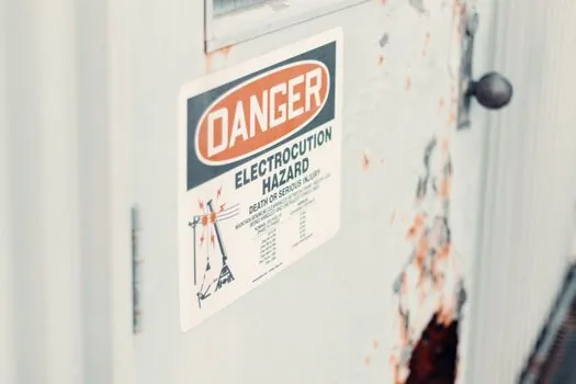
Do not maintain equipment that has been administratively retired, and do not test a cabinet that is missing its arc-flash label, since the incident energy is unknown. The IET Wiring Matters guidance is also explicit on the post-Covid reset: an installation left idle for a prolonged period must be re-commissioned, not just switched back on, because insulation, heaters, and SPDs have all drifted while unmonitored [S4]. For automatic molding line cells, the same reset logic applies, since heaters, hydraulic oil, and control wiring all degrade in a cool-down.
The next trackable signal is the 2026 revision cycle of NFPA 70B, which has shifted from a recommended practice to a standard, and the 2025-10 update on technician training pathways [S3]. Plants auditing their EPM should expect inspectors to ask for thermogram baselines, torque logs, and proof of EN 50110-1 or NFPA 70E procedure use on the next review. A related reference for spec-anchored selection in adjacent plant disciplines is the power grid BOM mapping across generation, T&D, and substations and the aerospace dust detector two-regime spec set, both of which use the same criteria-based comparison logic applied here to maintenance tasks.