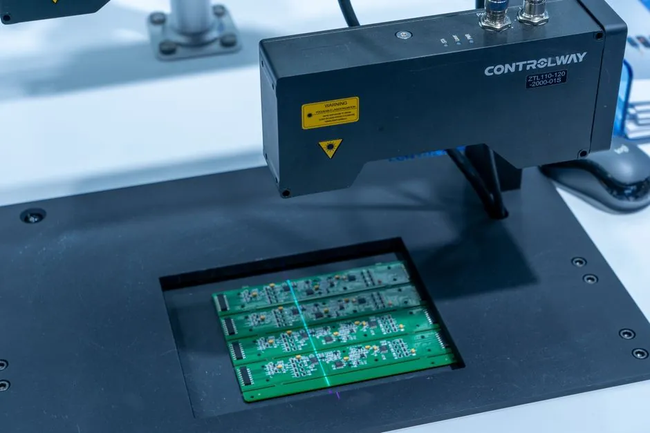
Handheld fiber laser welders in the 1000–1500 W class are now a standard fit for thin-to-medium stainless and aluminum work, but installation discipline still drives weld quality. A correctly commissioned 1200 W unit can hold a clean seam on 0.5–2.0 mm stainless steel [S2], while a rushed setup with impure cooling water or unfiltered shielding gas will pit nozzles and cloud protective lenses within a shift.
This walkthrough uses four published guides (RT Laser, Gweike, Xlaserlab, HARSLE, all 2024–2025) to map a real install sequence with the numerical thresholds vendors actually publish: gas pressure >0.2 MPa, gas flow >15 L/min, single-phase 110–220 VAC input, and roll-out of test coupons before any production run [S1][S3][S4].
Site Prep: Foundation, Ventilation, and Mains Matching
Place the welder on a stable ground or support, in a dry, well-ventilated room, and keep dust and swarf away from the optics path [S1]. For handheld fiber units, a flat bench rated for at least the head + wire feeder + gas cylinder is enough; vibration from adjacent stamping presses will mis-track the wobble head and show up as bead wander within minutes.
Match the mains before you lift the crate. The X1 Pro spec sheet calls out single-phase AC at 110–220 VAC, with supplied plugs rated 125 V/20 A and 250 V/16 A [S3]. Running a 220 V-rated unit on a 110 V drop will fault the laser source on under-voltage; running a 110 V-rated unit on 220 V will trip the input fuse. For shops already using three-phase, a step-down transformer or a phase-specific outlet is mandatory, not optional [S1].
Cooling Loop: Distilled Water, Level, and Monthly Exchange
Fill the integrated water tank with distilled or purified water to the indicated level; mineral-laden tap water deposits scale on the chiller heat exchanger and clogs the laser-diode cold plate [S4]. A weekly visual check of the level plus a monthly full drain and refill is the published cadence; shops that skip the refill typically see diode-temperature alarms after 4–6 months of two-shift use [S4].
Confirm the cooling circuit is closed and leak-free before energising the laser source. RT Laser's commissioning sequence calls for connecting the cooler to the laser source with the supplied accessories, verifying every fitting is secure, and then routing electrical and pneumatic lines in a way that prevents chafing [S1]. For a linear guide used in an adjacent automated welding cell, the same contamination logic applies: airborne cutting fines from a nearby station will shorten the life of any linear bearing inside the laser head's wobble mechanism.
Gas Circuit: Argon, Regulator, and the 0.2 MPa / 15 L/min Floor
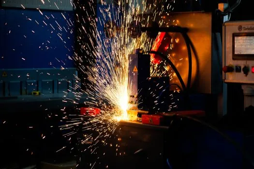
Shielding gas is the most-skipped step in handheld laser commissioning, and it shows up as porosity and soot on the first coupon. Connect the gas hose (6 mm OD) to the protective-gas inlet, open the cylinder, and verify the regulator delivers more than 0.2 MPa (2 kgf/cm²) with a flow rate above 15 L/min [S3]. For stainless steel, argon is the default; for aluminum, argon or argon/helium blends are common. HARSLE's tutorial specifies a pressure regulator on the argon tank and a flow adjustment before any test weld [S4].
Leak-check every fitting with a soap solution before firing the beam. A 1% leak at the regulator costs roughly 1–2 L/min of argon continuously, which is enough to push the local flow below the protective threshold and oxidise the weld pool. If the shop also runs a laser cutter on the same floor, dedicate a separate argon regulator and hose so peak draw from the cutter does not starve the welder.
Wire Feeder, Welding Head, and Safety Interlocks
Hardware install order matters: power cable first, wire feeder second, external emergency stop third, then gas, safety clip, and parameter setup [S3]. The X1 Pro wiring diagram shows the wire-feeder port directly below the power port, and the emergency-stop cable terminates at a DB-25 control connector that must be screwed down, not just inserted [S3]. A loose DB-25 is the typical root cause of a welder that "won't arm" on first power-up.
Wire-feeder setup is the step that traps first-time installers. Open the side cover, pull the two red buttons down, swap the feed roller to match wire diameter (0.8 / 1.0 / 1.2 mm are the common sizes), lock the red buttons back up, thread the conduit, set the wire through the torch, and hold the WIRE FEED button until the wire exits the nozzle [S3]. For operators moving from a crossed-roller guide manual head, the extra attention to wire straightness pays off: a 0.5 mm bend in the liner shows up as a wandering arc in the puddle.
Parameter First Pass: Continuous vs Pulse, Test Coupons, and Acceptance
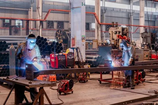
On the HMI, select continuous-wave mode for beads on butt joints and pulse mode for stacked or heat-sensitive thin sheet, then start with vendor-published presets [S3]. Gweike's 2025 guide lists 1000–1200 W as the practical floor for stainless under 3 mm and 1500 W+ as the recommended tier for aluminum because of reflectivity and thermal conductivity [S2].
Weld test coupons before any production part, and inspect for oxidation colour, undercut, and porosity [S1]. A gold-to-straw oxide tint on stainless is acceptable; heavy blue/black or soot means shielding gas is short. For shops already running a laser level for alignment, plumb a parallel reference so the test-coupon table and the production table share the same datum, which removes a hidden variable from acceptance data.
When to Stop, Escalate, or Re-Commission
Do not chase a bad weld by cranking power: most "bad welds" trace back to one of five causes, dirty surface, poor fit-up, unstable gas shielding, wrong travel speed, or an over-aggressive heat-input window [S2]. If two consecutive test coupons fail visual inspection, stop and walk the install checklist back from the top: gas pressure, water level, wire feed, then parameters. Repairs, not adjustments, are required when the protective lens clouds within a single shift (replace lens, then re-check gas filtration), or when the laser source throws a temperature alarm under no-load conditions (escalate to a service tech, do not bypass the interlock) [S4].
Trackable signals to watch over the next quarter: vendor firmware releases that add closed-loop gas monitoring, and the wider rollout of 6-in-1 workstations that combine welding, cutting, cleaning, and marking in one chassis [S2]. For facilities planning a second cell, the commissioning sequence documented here scales unchanged, and the same discipline applies when integrating a laser marker or a laser profiler into the same line. The reference path for adjacent processes, including the spec walkthrough in this truck crane testing and commissioning procedure field reference, uses the same staged-acceptance logic that a laser-welder install demands.