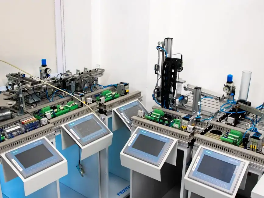
An EV-scale battery cell production line runs three sequential process blocks: electrode manufacturing, cell assembly, and cell finishing, with formation cycling appended as the electrochemical conditioning step [S1][S6].
For a greenfield 2026 design, the layout must accommodate parallel cathode and anode streams, a controlled dry room, stacking or winding stations, electrolyte filling, and a high-voltage formation and aging area sized for SEI layer build-up [S3][S6].
Three Process Blocks and Where Yields Are Won or Lost
The three-block structure is the industry reference: electrode manufacturing, cell assembly, cell finishing [S6]. Electrode production starts with slurry mixing of active material (NMC, NCA, or LFP), conductive carbon, and binder, then precision coating onto aluminum foil for cathodes and copper foil for anodes, followed by solvent drying and calendering to a controlled density [S1]. Calendering pressure and electrode density directly trade off energy density against internal resistance, so coating line speed is matched to drying oven length to lock a stable residual solvent window [S1].
Cell assembly takes the dried, calendered, and slit electrodes through notching, stacking (for pouch and prismatic) or winding (for cylindrical), tab welding, and pouch forming or can insertion [S1]. Cell finishing is electrolyte vacuum filling, vacuum sealing, and the formation cycles that build the SEI layer on the anode, which sets long-term cycle life and DC internal resistance [S1]. The formation step requires high-precision chargers and aging racks running 24-72 hours per batch, which becomes the throughput bottleneck for greenfield sites [S1][S7].
Cell Format Choice: Cylindrical, Pouch, and Prismatic Compared
Cell format is the first design decision and propagates through every downstream station. Cylindrical formats (18650, 21700, 32650, 26650) are built on high-speed winding machines and are the simplest to scale; prismatic cells use stacked electrodes inside a rigid aluminum can; pouch cells use a stacked jelly roll inside an aluminum-laminate film and demand the tightest forming and sealing control [S4]. For specification work, the same input data drives the line: cell dimension, unit cell design, chemistry, capacity in Ah, and nominal voltage in V [S4].
When comparing formats, four criteria dominate the selection: energy density at pack level, mechanical robustness, thermal management ease, and line CAPEX per GWh. Cylindrical cells are mechanically robust and ride high-speed winding but pack into modules with dead space; prismatic cells give the highest pack-level fill and a rigid can that simplifies module stacking, but require heavier stamping and laser welding stations; pouch cells deliver the best gravimetric energy density but need compression fixtures to manage swelling over cycle life. Sodium-ion lines largely mirror lithium-ion hardware but use aluminum current collectors on both sides, which simplifies material flow and removes one copper-anode track [S8].
Parallel Cathode and Anode Lines, and the Case for Physical Separation

EV battery plants run two separate parallel lines, one for cathode and one for anode, rather than one mixed line [S3]. The separation is functional, not just logistical: cathode and anode slurries use different solvents (NMP-based versus water-based for most graphite anodes), different foil handling, and different drying profiles, and cross-contamination from copper or anode carbon into a cathode line scrapes the entire affected batch [S3].
The natural physical split also lets the dry room and coating aisles be sized independently to each chemistry's solvent recovery load, which is a major OPEX line for any NMP-based cathode process [S1][S3]. A line-frequency furnace is not used for electrode drying, but the same controlled-atmosphere principle applies to any solvent recovery loop tied to the coater ovens. For lines planning solid-state or sodium-ion variants, the same parallel-track topology carries over, since the anode and cathode chemistries still differ in coating solvent, foil substrate, and calendering window [S5][S8].
Dry Room, Formation, and the Hidden Throughput Bottleneck
Lithium-ion cell assembly happens in a dry room held at a dew point below -40 degrees C, with relative humidity typically targeted under 1% to keep residual moisture in the cell low enough that the SEI layer forms cleanly [S1][S6]. Electrolyte filling is done under vacuum to drive wetting into the porous separator and electrode stack, and the cells are vacuum-sealed before they leave the dry room [S1].
After sealing, every cell runs through formation, which is a controlled initial charge-discharge sequence that builds the SEI layer, and then sits in aging racks for days while data is collected on self-discharge and capacity spread. This is where the line's true cycle time is set: coating can run hundreds of meters per minute, but formation capacity, measured in channels and rack slots, sets the WIP and the capital cost per GWh [S1][S7]. For 2026 capacity planning, formation is consistently the gating constraint, so new lines are sized by formation channel count first and coating speed second [S7]. Engineers evaluating cell sourcing from China should treat formation cycle time as a leading indicator of supplier throughput claims, since it is rarely published but always binds the cell output rate.
Material Handling, Automation, and Where the Load Cell Earns Its Place
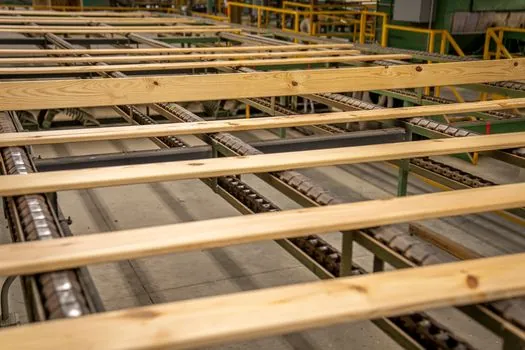
Material flow inside a cell line is dominated by precision web handling: foil tension, coating weight per square meter, and calendered electrode density all need closed-loop control, which is where load cell force measurement and load cell module integration show up in calender roll force, winding tension, and stacking pressure stations. Slurry mixing also depends on accurate weight batching at the front end, since moisture content and solids ratio set the coating window downstream [S1].
On the pack side, the same line then integrates laser welding, spot welding, and BMS testing stations, with a CCD visual inspector catching tab alignment and seal defects before cells enter the pack fixture [S4]. A modern automatic molding line is not part of the cell line itself, but battery tray and housing production for the pack side runs on the same lean principles: parallel tracks, inline test, and a clear data handoff at each station. For a process engineer reviewing a vendor's molding line proposal, the same throughput math applies: formation channels and molding machine clamp tonnage are both downstream capacity gates, not the headline coating or pressing speed. Sorting between good and suspect cells after formation is done on a conveyor sorting line tied to the formation data, which keeps reject cells from entering the pack [S4].
Scale-Up from Pilot to Gigawatt, and the 5-Step Sourcing Plan
Scale-up from a pilot line to a multi-GWh commercial line follows a well-documented life cycle inventory methodology: pilot data drives equipment sizing, which drives facility load, which drives OPEX and LCA boundaries [S7]. A 5-step sourcing methodology for lithium-ion or sodium-ion equipment is the standard pre-procurement flow: define cell format and chemistry, lock annual GWh target, map process steps to equipment, validate vendor FAT data at pilot scale, and finally negotiate commercial line ramp profile [S8].
The market context for 2026 remains skewed toward China-sourced equipment for prismatic and cylindrical lines, with European and North American integrators focused on turnkey and solid-state pilot lines [S4][S5][S8]. For grid-scale deployment downstream of the cell line, the grid-scale battery storage capacity snapshot provides a useful cross-check on whether announced cell capacity is being absorbed by stationary projects, which in turn tells the cell line designer whether the next 12 months will favor LFP prismatic or NMC cylindrical format orders. For procurement teams tracking this market, two signals to watch are sodium-ion pilot line announcements—where suppliers such as those offering dedicated sodium-ion battery production lines test new cell formats—and the migration of formation cycling onto higher-density rack systems that reduce the formation footprint per channel, as discussed in the broader context of building efficient battery assembly lines [S4][S5][S8].