
Thermally conductive silicone gap-filler pads and silicone potting compounds sit at the centre of EV battery-module thermal design, and IDTechEx tracks the global thermal interface materials (TIM) market at a 10%+ CAGR between 2026 and 2036, with EV batteries called out as the most cost-sensitive TIM application [S1].
Pads, gap fillers, and potting compounds are functionally different: a pad is a pre-formed sheet fitted between a heat source and a heat sink, while a potting compound is a liquid encapsulant that cures in place around a protection board or module sub-assembly [S2][S3]. The two products solve overlapping but non-identical problems, and the design error in 2026 is still to confuse thermal conductivity with total heat-dissipation capability.
TIM taxonomy: TIM1, TIM1.5, and TIM2 in a battery module
IDTechEx classifies thermal interface materials by location: TIM1 sits between a die or cell and its primary spreader, TIM1.5 sits between intermediate layers inside the module, and TIM2 sits between the module-level spreader and the cold plate or housing [S1]. In a prismatic or pouch-cell battery module the TIM2 layer is almost always a pre-formed pad or a dispensed gap filler, because the mating surfaces are large and the gap tolerance is driven by cell swelling over life.
The performance of any TIM is set by its filler system inside a polymer matrix. Common fillers in 2026 TIMs include alumina, alumina hydroxide (ATH), aluminium nitride (AlN), boron nitride (BN), zinc oxide (ZnO), and magnesium oxide (MgO), with higher-conductivity grades using silver, graphene, or carbon nanotube fillers [S1]. For battery modules the filler choice is dominated by cost and dielectric strength, not raw conductivity, which is why alumina and BN dominate cell-to-module interfaces.
Pre-formed silicone pads: handling, compression, and dielectric behaviour
Pre-formed thermally conductive pads are cut to size and fitted between the cell stack and the cooling plate, where they act as both a thermal bridge and a mechanical compliance layer [S4]. The trade-off, repeated across multiple vendor webinars, is that pre-formed pads are easier to install in low-volume builds but typically require manual placement, which is the cost driver on a high-volume pack line [S2].
Silicone is the dominant pad binder because it tolerates the -40°C to 85°C service range that automotive battery modules see, and silicone pads can be supplied in a wide range of thicknesses and compression levels so the same material family covers gap-filler, isolation, and slight-vibration-damping roles [S3][S4]. For dielectric isolation between a live cell tab and an aluminium cold plate, glass-reinforced silicone pads such as the CHO-THERM family were specifically developed as a user-friendly alternative to greased mica insulators used with discrete power devices [S6].
Potting compounds: low conductivity, but they are not a TIM

Silicone potting compounds are liquids that are metered and dispensed over a PCB or bus-bar assembly and then cure to a soft elastomer, locking out moisture and vibration. The mistake that battery engineers still make is to assume a potting compound also dissipates heat. As a 2026 process note from a power-battery PCB manufacturer puts it, potting compound thermal conductivity is low, and the compound traps heat inside the module rather than conducting it out [S3].
That is why potting compounds are specified for environmental sealing, vibration damping, and arc resistance, not for the cell-to-cold-plate thermal path. In the same 2026 reference, the author describes a real production failure where the potting compound reacted with the solder mask on the protection PCB and the surface blistered within six months, scrapping the whole module [S3]. The lesson is that potting selection has to be paired with a compatible solder mask and surface finish system, otherwise the encapsulation accelerates the failure it was meant to prevent.
Selection criteria: conductivity, dielectric, viscosity, cost, and dispense throughput
A 2026 spec comparison for battery-module thermal materials lines up against four criteria. Thermal conductivity: filled silicone pads and gap fillers typically reach 1.5-5.0 W/mK, alumina- and BN-filled grades cover most cell-to-module interfaces, while standard silicone potting compounds sit at roughly 0.2-0.4 W/mK and are chosen for sealing, not conduction [S1][S3]. Dielectric strength: glass-reinforced silicone pads are explicitly used as electrical isolation between live parts and heatsinks, replacing greased mica in power-device stacks [S6]. Viscosity and dispense: liquid gap fillers and potting compounds are metered through two-component cartridge or meter-mix systems, which removes the manual placement labour that penalises pre-formed pads at high volume [S2]. Cost: EV battery TIMs are the most cost-sensitive application in the IDTechEx 2026-2036 forecast, and the report's filler benchmark explicitly grades materials on US$/kg alongside conductivity, toxicity, CTE, dielectric strength, and density [S1].
On those four criteria the matrix is clear. Use a pre-formed silicone pad when the gap is well-defined, the line is low-to-medium volume, and the pad doubles as a dielectric insulator. Use a dispensed silicone gap filler when the gap varies across the pack, manual placement is not viable, and a slightly higher thermal resistance per dollar is acceptable. Use a silicone potting compound only where the function is sealing, vibration damping, or arc protection, never as the primary heat path out of the cells.
Use cases from EV battery packs and power electronics
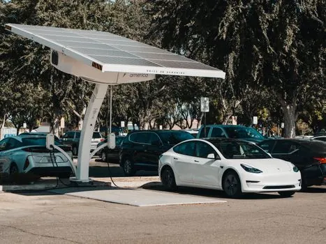
Parker's automotive webinars frame the same three-way decision for EV fleet batteries: TIMs improve heat transfer and battery life, dielectric coatings protect against arcing and let designers compress pack geometry, and encapsulating foams add durability and help reach safety targets [S5]. In other words, a production battery module in 2026 typically uses a TIM2 pad or gap filler for the cell-to-cold-plate path, a dielectric coating or insulating pad for live-to-ground isolation, and a potting or foam encapsulant for the protection PCB and bus-bar region.
That layered logic is also why the IDTechEx forecast segments TIMs by application, with EV power electronics singled out as one of the faster-growing pockets alongside data centres, ADAS, and advanced semiconductor packaging, on top of the already-large EV battery base [S1]. The same filler, alumina or BN, can appear in a TIM2 pad, a TIM1.5 gel, or a potting compound, but the designer's choice of which TIM family to use is set by the gap tolerance and the production volume, not by the filler itself.
Failure modes, sourcing, and what to watch next
The 2026 failure catalogue is dominated by interface problems, not bulk material failures. A 400 mm by 100 mm protection PCB on 1.6 mm FR-4 with end-only fixing bent visibly in road testing, cracked the inter-layer resin, and produced micro short circuits, a defect that no amount of copper thickness or potting compound would have prevented [S3]. A second, well-documented failure mode is intermetallic compound (IMC) growth at the nickel-tab weld, driven by the wrong surface finish, which makes the solder joint brittle within three to five years even when the PCB itself is correctly designed [S3].
For sourcing, the practical signal in 2026 is that EV battery TIMs remain the most cost-sensitive application in the market, so alumina- and ATH-filled silicone grades continue to dominate cell-to-module pads and gap fillers, while silver, graphene, and CNT fillers stay confined to power-electronics and advanced-packaging TIMs where the dollar per watt matters more than the dollar per kilogram [S1]. A second watch-item is potting-compound compatibility: spec teams should treat the solder mask, surface finish, and potting chemistry as a single coupled system, not three independent line items, to avoid the blistering failure mode reported in 2026 field data [S3].
Trackable next signals: the IDTechEx 2026-2036 TIM forecast will refresh area, mass, revenue, and unit-price splits for EV batteries and EV power electronics as 2026 cell-platform data lands, and any new filler or low-voiding pad line announced in the next two quarters will read against the same -40°C to 85°C, dielectric, and cost envelope that the 2026 field failures have already exposed.
For component-level specifications, see construction machinery and equipment, lamps and light fittings, and lighting equipment and electric lamps.
Related analysis: CC vs CV vs CR vs CP on a DC Electronic Load: Loop Behaviour, Use-Case Fit, and Selection.