
Battery management system manufacturing quality is decided at six line-side gates, not at end-of-line audit: incoming cell inspection, internal-resistance and capacity matching, controlled assembly, BMS threshold validation, full charge-discharge verification, and storage-safe dispatch at 50-60% state of charge [S3]. Skipping any gate shows up as imbalance, premature capacity loss, or a thermal event in the field, which is why BESS failure statistics and EV warranty data both trace back to BMS validation discipline more than to cell brand.
A BMS monitors cell voltage, current, and temperature in real time, runs State of Charge and State of Health estimation, and enforces protection functions on every lithium pack from 10 kWh residential units to 10 MWh grid systems [S2]. The same hardware block must protect LiFePO4 cells inside a 2.5-3.65 V per-cell window [S2] and hold LFP module temperature between 15 degrees Celsius and 35 degrees Celsius during operation [S5], so the manufacturing test plan has to cover both electrical and thermal thresholds, not just one or the other.
What "Quality" Means at the BMS Level
Every BMS shipped is validated against five protection thresholds: overcharge cutoff, over-discharge cutoff, cell balance trigger, temperature limit, and short-circuit response [S3]. These are not marketing claims, they are pass/fail tests on the populated PCB, with fault injection to prove the protection circuit actually trips rather than just reporting the fault.
The BMS has three concurrent jobs: act as a protection circuit against electrical and thermal damage, serve as a measurement system for voltage, current, temperature, SOC, and SOH, and function as a communication hub to the inverter, EMS, and monitoring platform [S2]. A pack that passes voltage tests but cannot stream cell-level telemetry to the EMS is, in modern BESS deployments, already a quality reject, because operators need cell-level data to schedule maintenance before a cell drifts into thermal runaway territory. The U.S. EPA explicitly notes that improvements in BESS quality and design have led to a decrease in failure incidents per gigawatt-hour deployed, even as installed base has grown [S1].
Cell-Level Spec Gates the BMS Must Enforce
The single most concrete number on a BMS datasheet is the per-cell voltage window, because going outside it, even briefly, causes permanent capacity loss [S2]. For LiFePO4 cells the safe range is 2.5 V to 3.65 V; for NMC and other Li-ion variants the windows are tighter at the top end, which is why cell chemistry must be declared before BMS firmware is frozen.
Thermal gates are equally hard. LFP modules in stationary storage are kept within 15-35 degrees Celsius during charge and discharge [S5], and the BMS has to throttle current, open contactors, or trigger cooling once any cell sensor crosses the limit. In EVs, the battery pack carries up to 40% of the total vehicle cost, and SOC/SOH/RUL estimation accuracy under transient loads and SOH forecasting during degradation remain bounded by model limitations and hardware processing capability [S4]. A BMS that quotes tight voltage windows but uses a slow ADC and a 1 Hz sample rate is not enforcing those windows in practice.
Manufacturing Line Gates: Incoming Inspection to Dispatch

A reproducible BMS-quality pack starts with incoming cell inspection, not at final test. Every cell batch is individually tested for capacity, internal resistance, and open-circuit voltage before it enters production; out-of-spec cells are rejected at intake rather than discovered later in a finished pack [S3]. This is the cheapest place in the line to remove a bad cell, and the most expensive place to miss one.
Cell matching and grading is the second gate, and the most consequential. Cells for each pack are matched by internal resistance and capacity within a tight tolerance band, because mismatched cells cause early capacity loss and imbalance that no BMS can fully correct in the field [S3]. Controlled assembly is the third: connection quality, cell orientation, insulation, and mechanical structure are each verified before the BMS PCB is installed, and there are no batch shortcuts on these steps [S3].
Gate four is BMS threshold validation, gate five is a full charge-discharge cycle to verify actual capacity against rated capacity, and gate six is final visual and electrical inspection plus dispatch at 50-60% SOC, the storage-safe window for long transit and shelf life [S3]. Packs that fail the capacity check are pulled for investigation rather than re-tested until they pass.
Chemistry Comparison: LFP vs NMC at the BMS Interface
The choice between LFP and NMC at the pack level sets four concrete BMS parameters: per-cell voltage window, thermal operating band, calendar ageing curve, and the cell-to-cell tolerance band the line can hold. LFP gives a wider 2.5-3.65 V window and tighter thermal requirements (15-35 degrees Celsius) [S2][S5]; NMC gives higher energy density but a narrower upper voltage limit, more aggressive cooling demand, and tighter matching tolerance because of faster calendar ageing. For a detailed look at the upstream cell-forming and dry-room loops that set the incoming cell quality feeding these gates, the battery electrolyte process control spec map is the right upstream reference.
Semi-solid-state cells shift the comparison further: lower thermal runaway risk because the electrolyte is not flammable, tighter cell-to-cell capacity and internal-resistance tolerance at the point of manufacture, more predictable ageing curves, and no liquid-electrolyte migration under vibration [S3]. For drone and high-vibration applications, that last point is a real BMS-quality lever, because vibration-driven internal resistance drift is one of the top field-failure modes a BMS sees in service.
EV and BESS: Two Different BMS Quality Stacks

EV BMS development pushes predictive and adaptive control, because SOC accuracy under transient loads, SOH forecasting during degradation, and real-time adaptability to driver behaviour are still constrained by model and hardware limits [S4]. Battery pack cost dominates (up to 40% of total EV cost), and thermal runaway under high-rate charging or harsh climates is a non-negligible risk, so the BMS has to do more than monitor, it has to predict [S4]. Automotive-grade certifications and quality standards add a measurable cost premium to BMS hardware, particularly for safety-critical applications [S6].
Stationary BESS has the opposite profile: lower per-pack energy density requirement, larger cell counts per system, and a fire-suppression problem that is structurally different from EV packs. Lithium battery fires are extremely difficult to extinguish and can reignite hours or days later, while battery fires can release harmful gases that pose health risks to nearby residents and first responders [S1]. Real incidents such as the May 15, 2024 Gateway Energy Storage fire (about 15,000 NMC lithium-ion cells, seven days of flare-ups) and the January 16, 2025 Moss Landing fire (1,200 residents evacuated for 24 hours) drive the EPA's BESS siting guidance [S1]. BESS deployment has grown rapidly but failure incidents per gigawatt-hour deployed have fallen, which is the right metric to track rather than absolute incident count [S1].
Charging Ecosystem and Why It Affects BMS Manufacturing Test
Charging standards fragment the BMS test matrix. CCS, CHAdeMO, GB/T, and Tesla's Supercharger protocol do not interoperate [S4], and next-generation paradigms such as V2G, V2V, wireless charging, and battery swapping further complicate both the protocol stack and the regulatory landscape [S4]. A BMS designed for one regional charging standard must be validated against a different fault profile than one targeting another, and the manufacturing test plan has to mirror that.
Regional disparities are wide. China leads in EV adoption supported by policy and dense charging networks; Europe follows with high market penetration in Norway, Sweden, and the Netherlands driven by emissions rules; the United States advances quickly but with regional disparities in charging access [S4]. For OEM procurement this means a "global" BMS line still has to be regionally qualified, and the validation gates above have to be repeated per target standard, not once for the world.
Limitations Buyers Should Engineer Around
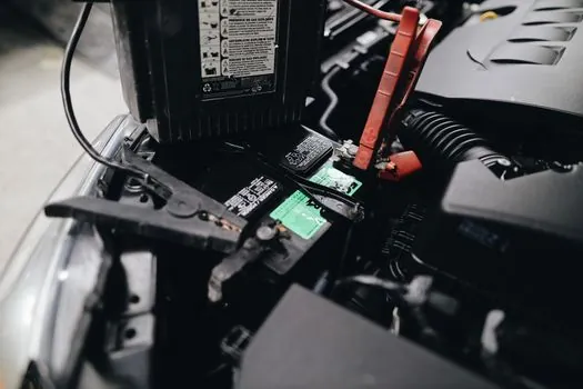
SOC estimation under transient loads, SOH forecasting during degradation, and real-time adaptability to driving or cycling behaviour remain bounded by model assumptions and hardware processing capability, regardless of BMS brand [S4]. A BMS spec sheet that quotes SOC accuracy to within 1% is only credible if the test conditions are stated, and most stationary BESS operating profiles will exceed those test conditions within a season.
Thermal runaway is a non-negligible safety risk under high-rate charging or harsh climatic conditions, and the BMS can only do so much if cell matching, mechanical assembly, and electrolyte filling were not controlled upstream [S4]. Manufacturing-quality signals worth tracking on the next vendor audit: incoming-cell OCV and internal-resistance distributions, the documented matching tolerance band, BMS threshold validation evidence per protection function, full-pack charge-discharge capacity data, and the dispatch SOC window.
For procurement teams building a spec sheet, two trackable signals are worth watching into late 2026 and 2027: published per-gigawatt-hour BESS failure-rate updates from EPRI, and any tightening of regional BMS validation requirements tied to the EV and BESS charging standards above. The EPA guidance page and the ScienceDirect EV BMS review are the two public artefacts to monitor for revisions.
Detailed specification references: energy management, additive manufacturing material, and air quality monitor.