
A Li-ion electrolyte filling station resolves to ±0.5% volumetric accuracy, ±0.01 g per-cell weight, and a leak rate below 10⁻⁶ mbar·L/s on the sealed cell, all under a dry room held at -40 to -60 °C dew point [S1][S5].
Across electrode coating, cell assembly, filling, formation, and aging, the control backbone is a PLC/SCADA platform with HART/4-20 mA field devices, ISA-style tag conventions, and a multifunction process calibrator used at loop commissioning to validate dew-point, vacuum, and load-cell chains against one transfer standard [S5].
Dry-Room Moisture as the First Control Loop
Cell and pack dry rooms are commonly specified at -40 to -60 °C dew point, equivalent to 10-60 ppm moisture by volume and below 1% RH at 20 °C, with cell-area electrolyte water content capped below 20 ppm to suppress LiPF₆ hydrolysis and HF attack on the SEI [S1][S5].
Capacitive polymer probes handle continuous monitoring because they tolerate the wider temperature swings of coating and calendaring halls, while chilled-mirror hygrometers are kept as the periodic reference since capacitive drift is the more common field failure mode [S1]. On prismatic turnkey lines, the dew-point sensor, the vacuum transducer, and the load-cell chain share the same PLC rack, and loop commissioning uses a portable process calibrator tied to a chilled-mirror reference rather than to factory nitrogen standards [S5].
Electrolyte Filling: Volume, Vacuum, and Wetted Materials
Commercial prismatic turnkey filling systems hold volumetric accuracy to ±0.5% of set volume, per-cell weight to ±0.01 g, and vacuum levels to ≤10 Pa, with soaking shelves running 8-24 h at ±2 °C temperature uniformity after injection [S5]. The reference range for a standalone filling skid is 5-50 mL per cell, 10-60 mL/s dispense speed, 1.0-1.6 MPa operating pressure, -0.08 to -0.1 MPa degassing vacuum, 15-35 °C electrolyte temperature, and 2-5 kW power draw, with a footprint of 2-4 m² [S2].
Wetted paths consistently use stainless steel 316L (ASTM A240) for the reservoir, PTFE or PFA for seals and piping, and ceramic rotary valves where the dose contacts the moving pump element; a polymer-cell R&D skid uses a stainless steel poppet with Teflon conical seat and PFA tubing throughout, with a 20 L stainless tank and ±1% single-stroke accuracy over a 0-174 mL range [S2][S4]. A rotary-table pouch-cell machine adds configurable multi-stage vacuum (up to 6 stages, ≤-0.090 MPa per stage) plus a leak-collection tray below the needle to catch drips before they reach the dry-room floor [S3].
Comparison: Pouch vs Prismatic vs Cylindrical Filling Architectures
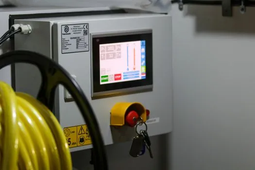
Selection on filling architecture runs along four axes: format rigidity, vacuum tolerance, soak behavior, and inline leak acceptance. Pouch cells require non-vacuum or shallow-vacuum filling because the foil stack collapses under deep vacuum; prismatic aluminum cases tolerate ≤10 Pa with full vacuum degassing; cylindrical hard cases sit between, with vacuum degassing done through the fill port before final crimp [S5][S7].
These four criteria map directly to instrumentation: pouch lines favor precision weight scales over vacuum transducers, prismatic lines need both a chamber vacuum gauge (≤10 Pa) and a load cell (0.01 g), and cylindrical lines lean on crimp-height force monitoring plus a helium-snug tester on a sampled basis [S5].
Electrolyte Preparation: Upstream of the Filling Cell
Electrolyte preparation for Li-ion salt blending and lithium battery electrolysis is controlled at 25-120 °C electrolytic temperature, 0-0.5 MPa pressure, and ±0.5% current stability, with 316L and PTFE as the dominant wetted materials to resist HF and LiPF₆ attack [S8]. The same preparation skid feeds the dry-room reservoir; temperature hold on the reservoir is set inside the 15-35 °C window to keep viscosity stable and to match the dispense head's calibration range [S2][S8].
Engineers sourcing preparation skids should treat the electrolytic temperature span, the pressure ceiling, and the current-stability percentage as the three bind-points; a ±0.5% current rating is the gating number for cells that will later be graded on DCIR spread during formation [S8].
Formation, Aging, and the Long-Duration Control Loop
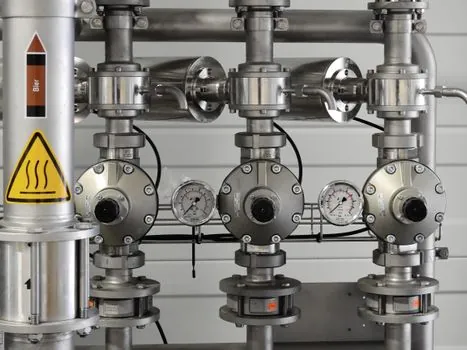
Formation is the longest single control step in cell production: a fresh cell is charged at 0.05-0.2 C to its formation voltage, held, and then cycled 2-5 times at 0.2-0.5 C to grow the SEI, with each channel of the formation cabinet logging voltage to ±1 mV and current to ±0.1% of full scale [S1][S5]. The cabinet's mass-flow-controlled N₂ or Ar purge holds O₂ below 1,000 ppm during formation to suppress fire risk, and the cabinet itself behaves like a two-hand control interlock in safety logic: the cell cannot be charged unless the door interlock, the channel contactor feedback, and the BMS hardware trip are all HIGH [S1].
Aging runs 7-21 days at 25-45 °C, with intermediate OCV measurements and DCIR screening, and cells outside the population's 3-sigma IR envelope are binned for second-grade use [S1]. On a pack line, the same 0.001 V voltage resolution and 0.001 mΩ internal-resistance resolution are used at end-of-line grading, with a 16-cell maximum stack height and post-stack pole-height difference held within tolerance before bus-bar welding [S5].
Selection Criteria: Filling Skid Specification Gates
A spec gate for an electrolyte filling skid should bind on at least seven values: filling volume per cell (5-50 mL), volumetric accuracy (±0.5% commercial, ±1% R&D), per-cell weight resolution (0.01 g), chamber vacuum (≤10 Pa prismatic, -0.08 to -0.1 MPa line-side), wetted material (316L + PTFE or PFA, ceramic rotary valve), leak-rate acceptance (<10⁻⁶ mbar·L/s), and PLC/SCADA interface with HART/4-20 mA field devices [S1][S2][S5].
Who it is for: cell makers scaling prismatic or pouch lines above 50 MWh/yr who need inline weight and leak data into a SCADA historian. Who it is NOT for: R&D labs running under 50 cells/day, where a tabletop liquid-injection machine with a 20 L tank, PFA piping, and ±1% accuracy over 0-174 mL is the cost-effective choice, and a separate vacuum oven handles the soak [S4][S6]. The filling skid is also the wrong place to control electrolyte chemistry: salt blending, moisture specification, and HF scrubbing belong on the upstream preparation skid, not on the dry-room dispense head [S8].
Sourcing, Standards, and Field Failure Modes
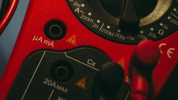
Engineers sourcing filling equipment should verify three documents: the manufacturer's PLC tag list mapped to ISA-style naming, the wetted-material certificate (316L per ASTM A240, PTFE or PFA seals), and the leak-test acceptance threshold tied to a helium-snug standard used for hermetic control valves on chemical service [S1][S2][S5]. The most common field failure modes are capacitive dew-point drift in the dry room, ceramic rotary-valve wear after 10⁶ strokes, and PFA tubing stress cracking at the dispense head fitting, all of which are caught only by a quarterly loop check against a multifunction process calibrator tied to a chilled-mirror reference [S1][S5].
For pack-line I&C, the same architectures feed the construction machinery and equipment and process control ecosystems that battery makers borrow from; engineers writing loop specs for filling cabinets routinely reuse PID structures, HART device descriptors, and alarm-trip templates drawn from lamps and light fittings and lighting equipment and electric lamps plant work, and pair those with inline defect-camera and IR-thermometer references for cell grading, as covered in an infrared thermometer spec gate and a battery separator Industry 4.0 inspection spec map [S5].