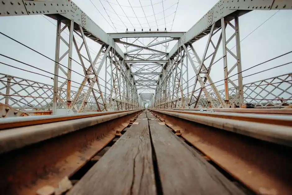
On a single girder overhead traveling crane, the hoist trolley rides directly on the bottom flange of one bridge beam, so flange width, flatness, and wheel load define both the lifting envelope and the service life of the runway rail [S1][S2].
Common single girder builds in the 0.5 t to 20 t range use either a rolled I-beam (wide flange) or a welded box girder, with a manual or electric monorail hoist trolley suspended from the bottom flange in the underhung configuration [S3][S4].
Flange as Running Surface: Geometry and Wheel Pressure
Bottom-flange running means the trolley wheels bear directly on the lower plate of the bridge girder, so the flange must simultaneously act as a structural tension chord and as a wheel-rail track with controlled hardness and flatness [S1][S4]. Wide flange I-beam girders are economical for short spans and lower capacities; as span and capacity grow, the bottom flange deepens, the dead weight per foot rises, and box girders with internal stiffeners become the lower-weight-per-foot alternative, with documented standard builds up to 140 ft span and 150 ton capacity [S4]. For a general primer on the crane family, see the single girder crane overview.
Top Running vs Underhung Trolley Configuration
In a top running single girder, the end trucks ride on rails above the runway beam, while the hoist trolley itself still travels on the bottom flange of the bridge; in an underhung crane, both the end trucks and the trolley hang from the bottom flange of the runway, which transfers all live and dead load into the building structure rather than the floor [S1][S4]. Underhung single girder cranes are the configuration of choice where headroom is constrained, because safety clearance below the ceiling is generally not required within the standard 16 t and 39 m envelope [S1].
Selection Criteria for a Bottom Flange Trolley

A bottom flange trolley must be matched to load, span, duty cycle, rail system, hoist type, and site conditions before any catalog code is selected [S5]. Wheel pressure and rail matching are the most common failure drivers: an undersized wheel diameter or a flange that is too narrow produces concentrated contact stress, premature wheel flange wear, and noisy travel [S5]. Motor power, reducer ratio, and travel speed should be sized to keep trolley acceleration below the slip limit on the rail head, typically with a safety margin of 1.5 to 2.0 times the steady-state rolling resistance; braking and end-of-travel limit protection are mandatory on any underhung single girder, and the working environment (dust, temperature, outdoor exposure) dictates seal class and lubricant grade [S5].
Comparison of Main Bottom Flange Trolley Options
Three trolley families dominate bottom flange service: the electric hoist trolley (compact, low cost, ideal for 0.5 t to 10 t and light duty), the open winch trolley (heavier drum, used where lift height or hook speed must be high), and the dual motor drive trolley (two driven wheelsets, used above roughly 10 t or on long cross-travels to spread load and reduce single-wheel slip) [S5]. On a single girder, the electric hoist trolley is by far the most common because the bottom flange carries the entire cross-travel reaction and the bridge itself limits hook approach dimensions; a double girder trolley rides on top of two girders and is generally not interchangeable [S5].
Standards Governing Single Girder Trolley Design

CMAA Specification 74 remains the definitive design reference for top-running and under-running single-girder electric traveling cranes that use under-running trolley hoists, and the November 2025 update to CMAA 74 reflects current advances in materials, controls, and load-handling technology [S6]. For a wider view of how the bridge structure interacts with the trolley and the runway, the overhead bridge crane reference covers girder selection and end truck interface. Buyers comparing single girder against double girder layouts at the 15 ton / 65 ft capacity line can use the single vs double girder decision guide to confirm whether a bottom flange trolley or a top-running double girder trolley is the right starting point.
Common Failure Modes and Maintenance Signals
Uneven trolley wheel wear, abnormal travel noise, unstable load swing, and premature flange-edge spalling on the bottom flange are the four most frequent indicators of a trolley that is mis-sized for the rail it runs on [S5]. On underhung single girder cranes, the bottom flange of the runway beam also acts as the wheel-rail surface for the end trucks, so any flange corrosion, weld spatter, or local deformation is a trolley problem as much as a structural one; daily visual checks of the flange edge and periodic gauging of wheel flange thickness are the two inspection items that most often catch a developing issue before it shuts the crane down [S5].
Trackable signals for the next planning window: vendor releases of CMAA 74 (2025 update) compliance data for specific bottom flange trolley models, and any manufacturer disclosure of standard wheel diameters, flange widths, and maximum permissible wheel loads for the 10 t to 20 t single girder envelope.
Spec-level background on the components involved: flange.