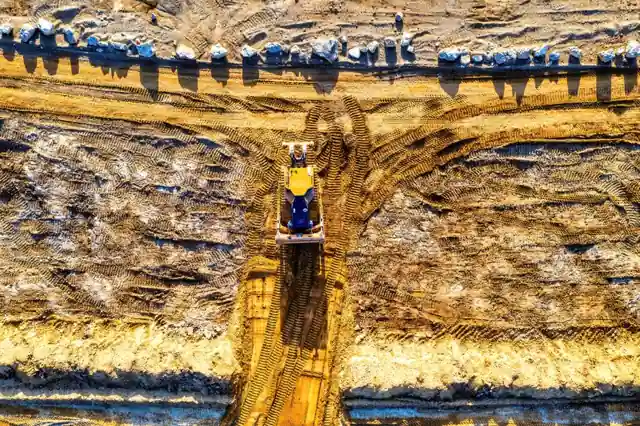
A crawler bulldozer is a track-laying, hydraulically actuated earthmoving machine: a diesel engine drives a hydraulic pump, torque converter, and planetary power-shift transmission; the same engine powers hydraulic cylinders that lift, tilt, and pitch the front blade, while final drives turn sprockets to walk the tracks [S2][S3].
Operating weights for mid-size crawler dozers in the HW16DS class sit near 17,550 kg with 131 kW @ 1850 rpm engines, 4.5 m³ blade capacity, and 1880 mm track gauge; ground pressure of 0.067 MPa is what keeps the machine from sinking in soft soils [S3].
Core Power Path: From Combustion to Track
The bulldozer power path starts at a high-torque diesel engine, typically delivering 100–300 kW depending on class, and routes through gear-driven and spline-coupled outputs to the working pump, the variable-speed torque-converting hydraulic system, and the steering pump [S2]. A hydraulic torque converter, planetary power-shift transmission, steering clutches, steering brakes, and final drives form the driveline that ultimately turns the sprockets [S2].
Final drive on most crawler machines is a secondary spur-gear reduction, with the sprocket acting as the output member; the chain of components is engine → coupling → torque converter → power-shift transmission → central transmission → steering clutch/brake → final drive → sprocket → track shoes [S2]. For comparison, mid-size dozers like the HW16DS produce roughly 150–160 kN of maximum drawbar pull from this driveline, which sets the upper bound on how much material a single pass can push [S3].
Track and Ground: Why Crawlers Dominate Soft Soils
Traction is the limiting factor in any dozer pass, and it is generated by steel grouser shoes biting into the ground rather than by wheel friction [S3]. Distributing the 17,550 kg operating weight over a 1880 mm gauge and a long track length on the ground keeps contact pressure at about 0.067 MPa, low enough to prevent sinkage on soft, sandy, or muddy terrain [S3].
Wheeled dozers exist but are a minority of the population; crawler machines do the bulk of land clearing, mining, and infrastructure work because of this ground-pressure advantage [S2]. On hardpan or rocky ground the grousers cannot bite, so a rear-mounted ripper is used first to fracture the surface and give the tracks something to push against [S3].
Hydraulics: How the Blade Actually Lifts and Steers
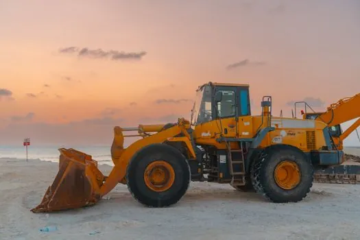
A hydraulic pump pressurises working fluid and feeds the lift, tilt, and pitch cylinders on the blade, and the same engine also drives a separate pump for the steering clutch and brake circuits [S1][S2]. Two joystick-controlled hydraulic valves regulate lift and tilt independently, so the operator can fine-grade to within centimetres without reblading.
Blade geometry is a passive but critical part of the working principle: a curved, rather than flat, moldboard rolls soil forward across the face, which lowers sliding friction and lets the machine move more cubic metres per litre of fuel [S3]. This is why a 4.5 m³ blade on a 17,550 kg chassis is a sensible pairing, and why simply upsizing the blade without matching weight and hydraulic flow usually produces wheel-spin rather than more production [S3]. For a deeper look at the pumps and valves that feed those cylinders, see the pressure-transmitter and industrial-valve reference pages.
Mechanical vs Hydraulic Transmission Split
Below roughly 102 kW (about 140 hp), many domestic crawler dozers, including the legacy T140, T120, and T70 classes, still use purely mechanical drivelines with clutch-and-gearbox shifting rather than torque converters [S2]. Above that threshold, the planetary power-shift transmission with hydraulic modulation is standard because it removes the shock loads that a manual clutch cannot absorb under full-blade load [S2][S3].
The practical difference for buyers: mechanical-drive dozers are cheaper, easier to field-repair, and dominate low-power fleets, while power-shift dozers cost more but let the operator reverse direction under load without burning the clutch, a key requirement for finish grading and short-push cycles [S2]. The bulldozer reference page covers the full machine taxonomy, while the flow-meter page explains how hydraulic flow is measured on these test stands.
Selection Criteria: Crawler vs Wheeled, and Where Rippers Fit
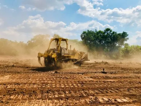
Pick a crawler dozer when ground pressure must stay below roughly 0.1 MPa, when slope work exceeds 30%, or when the material is loose sand, wet clay, or blasted rock; a wheeled dozer is acceptable only on finished surfaces with short cycle distances [S2][S3]. For mine-site and forestry haul-road work, the trade-off is closely related to ADT vs rigid hauler selection, because the dozer pushing at the face and the truck on the haul road must be matched on cycle time, not just bucket volume.
Add a rear ripper whenever the job includes weathered rock, hardpan, or frozen ground; single-shank rippers concentrate force for trenching, while multi-shank rippers cover a swath for bulk pre-loosening before the blade passes [S3]. On softer, pre-loosened ground a lighter dozer can match the production of a heavier one with no ripper, which is why operating weight and ripper fit, not engine kW alone, drive the specification. For drilling and blasting-adjacent work, rotary drilling rig selection follows a similar weight-to-bit-force logic.
Operating Limits and Failure Modes
The bulldozer working principle hits three hard limits in the field: track slip when grousers cannot engage, hydraulic stall when blade load exceeds pump flow at engine redline, and driveline shock when an inexperienced operator reverses direction under full load on a mechanical-transmission machine [S2][S3]. Each of these shows up as a different telemetry signature: high engine rpm with low ground speed means track slip; rising hydraulic pressure with falling engine rpm means blade overload; and sudden torque-converter outlet temperature spikes mean clutch abuse [S3].
Preventive maintenance is therefore tied directly to the working principle: track tension must hold grouser engagement, hydraulic fluid must stay within ISO 4406 cleanliness targets to protect the working pump, and the torque-converter outlet temperature should be trended because it is the earliest indicator of driveline stress [S2]. Ignoring any of these turns a normal wear item into a frame-off rebuild, which is why fleets log drawbar-pull tests and hydraulic-pressure curves rather than only engine hours. Inputs from the pressure-sensor and PLC pages explain how those signals are captured and trended in modern telematics.
Track the next signal: any 2026–2027 revision to Tier 4 Final / Stage V emissions curves on mid-size dozers in the 100–200 kW band, and the introduction of electric-drive dozer prototypes, will directly change the driveline architecture described above; both are worth monitoring before specifying a new fleet.