
A busway is a prefabricated, enclosed assembly that houses copper or aluminum busbars and distributes power between loads; a fuse is a single overcurrent-protection element sized by continuous current (A) and interrupting rating (kA), typically installed inside a fuse holder or a bus plug tap-off unit [S1][S3].
Specifying one without the other is the most common procurement error on 600 V class power distribution runs, because the busway sets the available fault current while the fuse sets the let-through energy and the coordination curve with upstream devices [S2].
Busway, Bus Duct, Busbar: the Three Meanings That Get Conflated
A busbar is the rigid metal strip (copper or aluminum) mounted inside switchgear, with typical ratings from a few hundred amps up to more than 10,000 A in generation equipment, while a bus duct or busway is the factory-assembled, enclosed trunking system that carries those conductors between rooms, MCCs, or data-center whips [S1][S2].
Copper busbars offer the lowest resistance and the highest thermal headroom but weigh more and track LME pricing; aluminum busbars carry roughly 60% of copper's conductivity at one-third the weight, which is why they are routinely tin- or silver-plated at joints to control contact resistance [S2]. The busway adds the steel or aluminum housing, the plug-in tap-off openings, the hangers, and the elbows, which is why the same 800 A run can be ordered as a "bus plug" system in feeder or plug-in configurations on Square D I-Line, Siemens Sentron, GE Spectra, or Eaton Pow-R-Way families [S3].
What a Fuse Actually Does on a Busway Run
A fuse mounted in a bus plug interrupts current when the amperes through the device exceed its continuous-current rating, and the door of the bus plug mechanically interlocks in the ON position so the fuse cannot be withdrawn under load on most modern plug-in units [S3].
Coordination is the real engineering job: the fuse's clearing I²t at the available fault current must be below the busway's mechanical withstand (typically 50 kA or 100 kA short-circuit rating for low-voltage feeder busway) and the I²t damage threshold of the downstream cable or bus plug, otherwise the protective device "saves itself" while the bus duct deforms. Class J, Class L, and Class RK1 fuses are the most common choices on 600 V North American bus plugs because of their 200 kA AIC ratings and current-limitation behavior, while IEC projects typically use NH or BS88 gG/aM links inside the same bus-plug housings [S3].
Decision Matrix: When Busway With Fuses Wins, and When It Loses
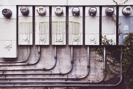
Use a busway with fused bus plugs when the load is 100 A to 1,200 A, distributed along a long run that will be re-tapped as the plant changes layout, and when the available fault current is between 10 kA and 100 kA symmetric; in that range a fused plug gives the lowest let-through energy and the smallest arc-flash incident energy at the tap point [S1][S3].
Choose a molded-case circuit breaker instead of a fuse inside the bus plug when the building operations team insists on resettable single-phasing protection or when remote tripping via shunt trip is required; fuses win on raw current-limitation, AIC-per-dollar, and coordination with the upstream fuse when selectivity is the design driver, but lose on convenience and on the ability to test with a button rather than a test stick. For runs above 1,600 A to 5,000 A, the busway size is governed by the housing and the plug-in window count, not by the fuse, and most OEM catalogs stop offering fused plugs much above 1,200 A, which is the hard cut-over point for specifying a bolted-pressure switch or a power circuit breaker instead [S3].
Copper vs Aluminum Bus Conductors Inside the Same Housing
That extra aluminum cross-section drives the bus-plug window dimensions, which is why a 100% copper bus plug does not always fit an aluminum housing retrofit and why OEM cross-reference tables (Square D I-Line to Siemens Sentron, GE Spectra SB to Eaton Pow-R-Way III) are length-matched and ampacity-matched separately [S3]. For data-center and high-rise vertical riser applications where weight on the structure matters, aluminum-housed busways are now common at the 2,500 A to 5,000 A range; for rooftop or outdoor industrial feeder runs, copper is still preferred because the joint count over a 30-year service life is the dominant reliability variable, and copper-to-copper bolted joints age better than copper-to-aluminum bimetal joints.
Plug-in Density, Tap-off Units, and Reconfiguration Cost
Feeder busway typically provides tap-off points every 600 mm to 1,200 mm along the run, while plug-in busway is offered with 2 to 6 plug-in windows per 3 m section, and that window density is the parameter that defines how often a load can be added or moved without extending the run [S2].
A typical tap-off unit ("bus plug") carries a fused switch or a thermal-magnetic breaker sized 30 A to 1,200 A in the same form factor, locks onto the busway housing with a grounding jaw that engages before the phase jaws, and is the only place in the system where the fuse actually performs its protective function on the busway [S3].
Standards, Ratings, and the Two Failure Modes That Hurt Most
The two failure modes that drive busway-with-fuse retrofits are (1) a single-phasing event where one fuse clears and the three-phase motor load keeps running on two phases, and (2) a coordination miss where the downstream fuse clears before the upstream, blacking out a healthy bus plug that should have stayed closed [S3].
Single-phasing protection is not built into a fuse; it requires either a three-pole disconnect with a fuse-per-phase plus a differential relay, or a molded-case breaker with phase-loss logic, which is why the specifier has to make a deliberate choice between convenience and protection depth at every bus plug. Standards governing this equipment include UL 857 (busway) and UL 248 (low-voltage fuses) in North America, and IEC 61439-6 (low-voltage busway assemblies) plus IEC 60269 (low-voltage fuses) on IEC projects; short-circuit withstand is verified by test, and published values for feeder busway in this class are commonly 50 kA, 65 kA, 100 kA, and 150 kA symmetric at 600 V [S1][S2][S3].
Track these signals before the next retrofit: (a) the OEM cross-reference between Square D I-Line II, Siemens XL-X, GE Spectra SB, and Eaton Pow-R-Way III plug-in windows, because plug compatibility governs the spare-parts inventory a plant must hold; and (b) the 2026 update to plant load growth and the count of unused plug-in windows still open along each run, because that is the single number that predicts whether the next machine install will need a shutdown or just a new bus plug [S3]. For broader architecture context, see the busway selection criteria map for 2026 and the SPD vs switch-disconnector decision map for the upstream side of the same feeder.
Spec-level background on the components involved: pressure transmitter.