
An SPD is a parallel-connected protective device that limits transient surge voltages to a level the downstream equipment can withstand, with common discharge ratings from 20 kA per phase up to 100 kA for Type 1 lightning-current arresters [S3][S1]. A surge protector contains non-linear components — typically metal-oxide varistors (MOVs), gas discharge tubes (GDTs) or transient voltage suppression (TVS) diodes — that switch from high-impedance to low-impedance state once the line-to-line or line-to-earth voltage exceeds its clamping threshold, then resets after the surge passes.
A switch-disconnector is a mechanical switching device that carries and interrupts load currents under normal conditions and provides a verified isolation distance in the open position. It is specified in series with the circuit and is judged on rated insulation voltage (Ui), rated operational current (Ie at AC-22/AC-23 duty), short-time withstand current (Icw), and the positive opening operation of its main contacts — it does not, by itself, clamp surges.
Core Function: Clamping vs Isolating
SPDs and switch-disconnectors solve different electrical-engineering problems and therefore sit at different points in the single-line diagram. The SPD is a parallel, voltage-limiting device that diverts surge current to earth and clamps the let-through voltage (Up) to a value below the impulse withstand of the protected equipment; the switch-disconnector is a series, current-breaking device that establishes a safe, visible isolation gap to permit lock-out/tag-out work on downstream circuits [S1].
ABB's low-voltage product taxonomy treats surge protection as a dedicated category distinct from switching and isolation devices, with SPDs categorised under IEC 61643-11 Type 1/Type 2/Type 3 classes based on installation location and discharge capacity (In, Imax, Iimp) [S1]. Bourns frames the SPD as an integrating assembly that combines discrete circuit-protection components (MOV, GDT, TVS) to deliver an enhanced level of protection for sensitive electronics, rather than as a switching or isolation element [S2]. Because the two functions do not overlap electrically, plant single-line diagrams typically show the SPD upstream of the switch-disconnector, with the disconnect providing a means to safely replace or test the SPD modules.
Selection Criteria That Separate the Two
When the question is "which device do I need?", the deciding parameter is the electrical fault mode you are mitigating. For transient overvoltage — lightning strikes, utility capacitor-bank switching, or induced surges from VFDs — the answer is an SPD sized to the system's maximum continuous operating voltage (Uc), prospective short-circuit current at the point of installation (Isccr), and the impulse current it must divert (Iimp for Type 1, Imax for Type 2) [S1]. A representative commercial unit such as the 20 kA SPD (model Ly5-D20) is rated to discharge 20 kA of 8/20 µs waveform surge current per phase, suitable for sub-distribution board mounting [S3].
When the question is "how do I isolate this circuit for maintenance or for an emergency stop?", the answer is a switch-disconnector sized to the load's rated current and switching duty. Key parameters are the utilisation category (AC-21 for resistive loads, AC-22 for mixed resistive/inductive, AC-23 for squirrel-cage motors), Icw for short-circuit withstand, and the mechanical/electrical endurance (number of operations under load). The two devices are routinely specified together — the switch-disconnector upstream of an SPD allows safe cartridge replacement; the SPD upstream of a switch-disconnector protects the disconnect's control electronics from induced transients [S2].
Installation Location and Coordination
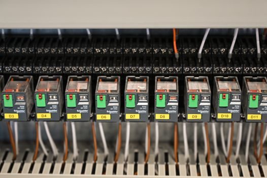
Coordination between SPDs and switch-disconnectors follows a clear spatial rule. Type 1 SPDs are installed at the service entrance to handle direct lightning currents and partial lightning currents, with Iimp values of 12.5 kA (10/350 µs) per phase common for residential/commercial service entrance applications and up to 25 kA (10/350 µs) for exposed structures. Type 2 SPDs are installed at sub-distribution boards, with In ratings of 5–20 kA (8/20 µs) and Imax of 10–40 kA. Type 3 SPDs are point-of-use devices with low Up values, installed close to sensitive terminal equipment [S1].
A backup fuse or a coordinated switch-disconnector is typically required upstream of an SPD so the SPD can be safely disconnected if it reaches end-of-life in a short-circuit condition. Bourns' technical documentation explicitly lists miniature switches, thermal cutoffs and thermal sensing among the discrete protective components integrated into SPD assemblies, but the upstream isolation function is fulfilled by a separate mechanical switching device, not by the SPD's internal thermal disconnect alone [S2]. On the downstream side, the switch-disconnector that feeds a motor or a feeder panel benefits from Type 2 SPD coordination on its supply side to prevent contact welding during indirect lightning events.
Decision Matrix: Choose by Fault Mode
For a spec-driven comparison on four criteria — fault mode addressed, electrical connection, key rating parameter, and typical location — the two device classes line up as follows. (1) Fault mode: SPD addresses transient overvoltage; switch-disconnector addresses load switching and isolation. (2) Connection: SPD is wired in parallel (line-to-line or line-to-earth); switch-disconnector is wired in series. (3) Key rating: SPD's primary rating is discharge capacity (Iimp / Imax / In) and voltage protection level (Up); switch-disconnector's primary ratings are Ie per utilisation category, Ui, and Icw. (4) Location: SPD at service entrance (Type 1) → sub-distribution (Type 2) → equipment terminals (Type 3); switch-disconnector as main isolator at panel incoming, as maintenance disconnect at each machine, or as emergency stop in motor control circuits. [S3]
A common confusion in panel design is treating the two as alternatives — they are not. Specifying a Type 2 SPD in place of a switch-disconnector leaves the panel with no safe isolation means; specifying a switch-disconnector in place of an SPD leaves the downstream electronics exposed to let-through surges in the kilovolt range during a lightning event. The economic ratio in a typical low-voltage panel is roughly one switch-disconnector per feeder plus one SPD per protection zone, not one-or-the-other. Similar logic applies in adjacent protection domains — see the selection logic in Circuit Breaker vs Contactor: Spec-First Selection Map, where each device again addresses a different electrical fault mode rather than competing for the same slot.
Standards and Compliance Boundary
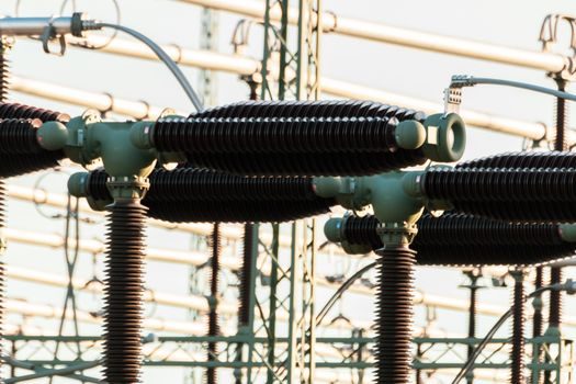
SPDs for low-voltage AC installations fall under IEC 61643-11, which defines Type 1/2/3 classification, test waveforms (10/350 µs for Type 1, 8/20 µs for Type 2/3), and the mandatory marking of Uc, Up, In/Imax/Iimp on the device body. ABB's surge-protective-device product range is positioned explicitly under this IEC framework and the parallel UL 1449 standard in North America, with installation location determining the Type class required [S1]. Bourns publishes surge-protective devices in compliance with REACH, RoHS, TSCA, PFAS, and PFOS/PFOA substance regulations, and the company's certification page lists applicable IEC and UL standards for each SPD family [S2].
Switch-disconnectors fall under IEC 60947-3, which defines utilisation categories AC-21, AC-22, AC-23, the rated insulation voltage Ui, the impulse withstand voltage Uimp, and the conditional short-circuit current Icc with associated backup fuse or breaker. Compliance with the positive opening requirement (marked with the IEC symbol on the device) is mandatory for emergency-stop and safety-isolation duties. Where the SPD and switch-disconnector are co-ordinated in a motor-control or PV-disconnect application, the relevant standards chain is IEC 61643-11 (SPD) + IEC 60947-3 (switch-disconnector) + the application standard (e.g. IEC 60364 for fixed installations, IEC 60204-1 for machinery electrical equipment).
Limitations and Failure Modes
SPDs degrade with every surge they clamp. End-of-life failure modes are (a) thermal runaway leading to disconnection by the internal thermal fuse, (b) open-circuit failure where the MOV loses clamping ability but does not indicate a fault to the operator, and (c) short-circuit failure that requires an external fuse or back-up breaker to clear. For this reason SPDs are routinely paired with a status indicator and a coordinated disconnecting device — typically a fuse or a switch-disconnector — so the user sees the SPD has reached end-of-life and can replace it without line work on a live busbar [S2]. The 20 kA commercial SPD cited earlier is built as a DIN-rail module with a pluggable cartridge, which assumes the upstream isolator is a separate device [S3].
Switch-disconnector failure modes are mechanical — contact welding from a short-circuit event exceeding Icw, wear of the main contacts past the manufacturer's electrical-endurance count (typically 6,000–10,000 operations for AC-23 duty), and failure of the positive-opening linkage. They do not degrade from surge exposure the way an MOV does, but they do need surge protection on their control-supply terminals if those terminals are exposed to induced transients. The economic failure profile of the two devices in a typical industrial panel is therefore: SPDs scheduled for periodic replacement at 5–10 year intervals or after a known surge event; switch-disconnectors replaced at end-of-mechanical-life, with no surge-driven replacement schedule.
When Each Device Is and Is Not the Right Answer
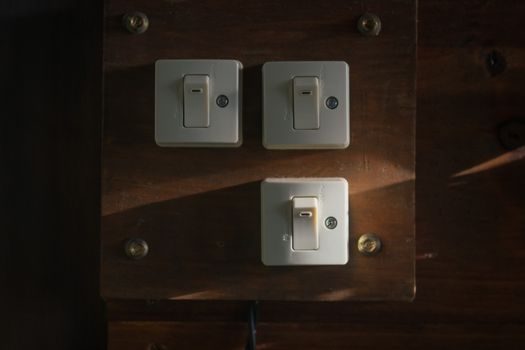
An SPD is the right answer when the load is sensitive electronics — PLCs, drives, instrumentation, network switches, medical equipment — and the failure mode being mitigated is a transient overvoltage, not a continuous overvoltage. It is not the right answer for overcurrent protection, for isolation of a circuit for mechanical maintenance, or as a substitute for a circuit breaker. A switch-disconnector is the right answer when the function is on-load switching of a feeder, local isolation of a machine for servicing, or emergency-stop switching; it is not the right answer for surge clamping, overcurrent interruption (use a circuit breaker), or as the sole protection for sensitive electronics on a known surge-prone supply. [S2]
For an industrial Ethernet cabinet fed from a switch-disconnector in a plant with overhead exposure, the typical coordinated specification is Type 1 SPD at the building entrance, Type 2 SPD at the MCC incomer, and a switch-disconnector immediately upstream of the Ethernet switch panel for maintenance isolation. The same single-line logic appears in adjacent spec domains such as Industrial Ethernet Switch vs Fieldbus Gateway: Spec-Driven Selection Map, where protection and isolation are treated as separate, stackable decisions rather than substitutes.
Spec-level background on the components involved: protective clothing.