
Cable gland failure is a documented field failure mode in brownfield PLC retrofits, and the gland part number is fixed by the existing enclosure hole pattern rather than by the new controller's I/O list.
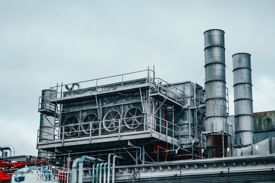
A brownfield retrofit on a pre-existing control cabinet typically means adapting to legacy PG threads and metric threads coexisting on the same back-plate, accommodating mixed cable diameters from retained analogue pressure transmitters and flow meters alongside new Ethernet runs, and commonly upgrading the enclosure's IP rating to IP65 or better to match the upgraded control system requirements.
Why the Existing Envelope Dictates the Gland Choice
In a brownfield PLC upgrade, the cable gland part number is constrained by the hole pattern already drilled in the enclosure, not by the new controller's preference. Legacy panels built before the mid-2000s typically use PG threads (PG11, PG13.5, PG16, PG21) and metric threads (M20, M25, M32) coexisting on the same cabinet, which forces the retrofit engineer to order parallel gland families rather than standardise on one family [S5]. The gland's mounting hole diameter, thread length, and PG-versus-metric designation must be confirmed before sizing the cable OD range; M20 brass glands from one manufacturer accept 12.3-20.0 mm cable OD with 10 mm thread length, M25 takes 20.4-27.0 mm, M32 takes 26.5-33.5 mm, M40 takes 33.0-41.5 mm, M50 takes 44.0-54.0 mm, and M75 takes 67.5-78.5 mm, with thread length rising from 10 mm on the small sizes to 15 mm on M40 and above [S2].
Four Sizing Inputs That Drive the Gland Part Number
Sizing a gland correctly for a PLC retrofit reduces to four measurable inputs: cable outside diameter (OD), armour diameter for SWA cable, enclosure hole diameter, and the IP/pressure rating of the target zone [S1][S5]. For unarmoured signal cables to analogue pressure sensors and flow meters, the gland's inner sealing ring range must bracket the cable OD with roughly a 0.1-0.5 mm compression margin, not the maximum OD of the cable family, since a too-loose inner seal is the typical cause of moisture wicking into the enclosure. For armoured power feeds to servo drives and VFDs, the armour diameter drives the inner cone selection while the outer jacket OD drives the outer seal; mismatching these two diameters is the leading cause of pull-out failure during thermal cycling [S6].
Material, Type, and Applicability Comparison for Retrofit Duty
Brass, stainless 316L, and nylon (polyamide) dominate the retrofit gland market, and the choice is driven by corrosion, mechanical strength, Ex certification availability, and unit cost rather than by the gland's published IP rating. Brass is the default for indoor control panels and armoured cable in oil and gas, scoring high on strength and Ex availability, medium on corrosion resistance, and low on cost [S6]; stainless 316L scores high on corrosion, high on strength, high on Ex availability, but high on cost, and is mandatory for chloride, washdown, and offshore service; nylon (PA66) scores high on cost and low on weight, but low on corrosion and is not generally available with ATEX/IECEx certification, so it is restricted to unarmoured signal cables inside dry, non-hazardous indoor rooms. For a brownfield PLC upgrade the practical rule is brass or stainless for the cabinet-to-servo motor power feed, EMC-rated brass or stainless for VFD output cables, and nylon acceptable only for cabinet-to-pressure transmitter 4-20 mA runs in non-Ex indoor locations; nylon is NOT appropriate for outdoor, washdown, or any classified hazardous area, regardless of its IP68 rating on paper.
Hazardous-Area Marking and the EN 62444 Anchor
Any gland installed in a Zone 1 or Zone 21 area during a PLC upgrade must carry traceable Ex marking, and the standard reference chain is non-negotiable. EN 62444:2013 is the construction standard that applies to cable glands across most UK and EU industrial installations, including non-hazardous ones [S4]. For hazardous areas, IEC 60079-0 and the IEC 60079-part-series govern Ex construction, with the gland's marking string such as "II 2G Ex db eb IIC Gb" for gas atmospheres or "II 2D Ex tb IIIC Db" for dust atmospheres defining the protection level and equipment group [S3]. The service temperature band printed on the gland (commonly -40 °C to +100 °C for Ex db eb IIC units) must sit inside the PLC cabinet's worst-case internal temperature, and a certificate such as ATEX ITS 16 ATEX18432X or IECEx ITS 16.0019X is a prerequisite for hazardous-area retrofits; an installer accepting a gland that lacks both certificates is exposing the new controller to a documented compliance gap.
EMC, VFD Proximity, and Signal Cable Routing
Cable gland selection affects electromagnetic compatibility (EMC) more than most retrofit specifications acknowledge, and the PLC upgrade is the moment this surfaces. Power cables feeding servo drives and VFDs act as common-mode noise sources that couple into parallel 4-20 mA loops from pressure transmitters and flow meters through any gland-to-enclosure bonding discontinuity [S2]. EMC-rated glands with 360° armour termination address this by providing a low-impedance bond from the cable screen (or armour) to the enclosure wall, and they should be specified on every VFD output cable and on every analogue signal cable that shares a tray with motor power. Per IEC 60079-0 guidance, the interface between the sealing ring and the enclosure wall shall be parallel and smooth to ensure the IP rating of the enclosure is maintained [S3]; the same flatness condition is what allows the EMC bond to remain stable over thermal cycling.
Installation Discipline: Torque, O-Ring, and Inspection Access
The most common field failure during a PLC upgrade is not the wrong gland on paper but a correctly specified gland that was over- or under-tightened, or that was installed with the wrong O-ring. Installation must be carried out by a competent person following local regulations and the manufacturer's torque table, and torque-wrench trace records are a typical audit request during retrocommissioning sign-off [S1]. For moving applications such as the cable between a servo motor and its junction box, an additional locknut secures the gland against vibration, while for static panels in a wet or outdoor environment an O-ring on the gland-to-enclosure interface enhances the IP seal [S1]. For hazardous-area glands, the selection checklist also requires that the gland have no mixed-up or loose parts and that it be inspectable with common tools, since glands inside Ex db enclosures must remain verifiable throughout the PLC asset life [S3].
Trackable signals for the next 90 days: (1) whether the plant's hazardous-area classification has been re-issued since the PLC upgrade, since ATEX/IECEx gland certification must match the re-issued zone map; (2) whether legacy PG-thread adaptors are stocked, because most retrofit projects underestimate PG-to-metric adaptor lead times; and (3) the as-built torque values recorded per gland, since torque-traceability is the single document an inspector will ask for first.