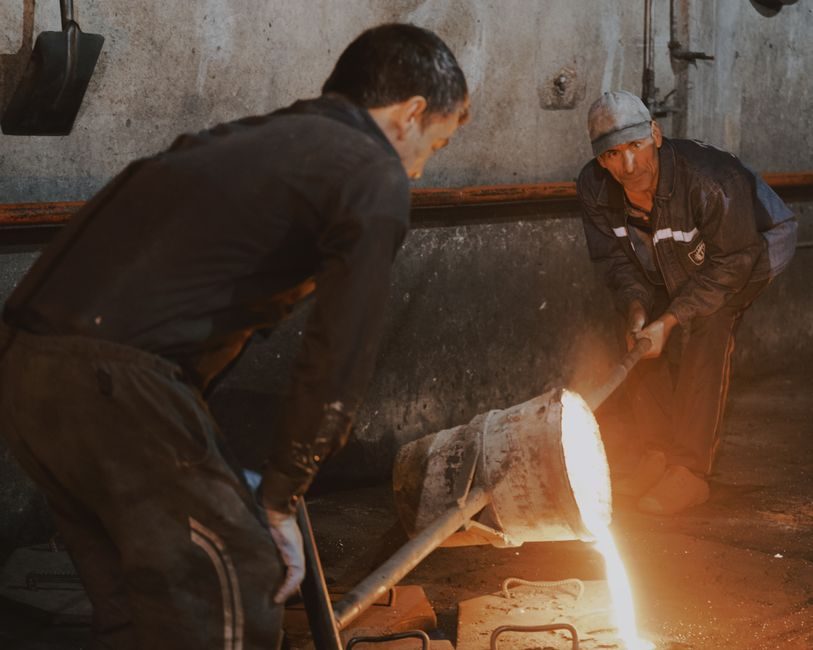
A casting ladle is the workhorse vessel between furnace and casting mold in any foundry or steelworks, with working capacities spanning roughly 1 t bench-ladle units up to 300+ t torpedo or slag-slag ladles used in integrated steel plants.
Selection hinges on steel/iron grade, pouring temperature window, refractory lining life per campaign, and overhead crane capacity — the four parameters a process engineer locks before quoting a ladle build or a die-casting machine cell.
Ladle Functional Classes and Capacity Bands
Ladles are classed by pour mechanism and duty: hand-pour bench ladles (≤2 t) for copper alloy and small iron job-shops, geared-swing ladles (2–30 t) for general iron work, and bottom-pour or stopper-rod ladles (30–300 t) for steel sand-casting mold and continuous-casting tundish feed [S1].
Working capacity typically equals 70–85% of nominal geometric capacity to leave freeboard for slag, swell during tapping, and emergency slide-gate closure, with pouring rates from 0.5 kg/s (small copper) to over 1500 kg/min (ladle metallurgy furnace tapping).
For sand-casting iron, geared ladles with manual or hydraulic tilt cylinders dominate because the pour stream must be trimmed visually — gear ratios of 1:18 to 1:32 give the operator enough mechanical advantage to hold a 1.5 t ladle at 30° stream-off without fatigue.
Refractory Lining Systems and Campaign Life
Three lining families cover 90% of foundry duty: high-alumina (Al₂O₃ 60–85%) for iron and non-ferrous, dolomite and dolomite-carbon for clean-steel ladles, and MgO-C (magnesia-carbon 5–18% residual carbon) for high-temperature steel transfer above 1650 °C [S1].
Working-lining thickness typically runs 150–250 mm in the barrel and 200–300 mm in the impact zone, with 50–80 mm of safety/insulating wool behind; monolithic safety linings are gaining share over brick because they eliminate the 4–6 mm mortar joints that initiate slag penetration.
Campaign life on a 30 t steel ladle averages 60–90 heats with dolomite and 100–150 heats with MgO-C, against 200–400 heats on a 300 t integrated-mill ladle where thermal mass dominates wear; preheating to 1100 °C minimum and gas-purging practice both add 20–30 heats per campaign.
Pour Control, Stream Quality, and Teeming Performance
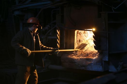
Bottom-pour ladles with alumina-graphite collector nozzles and slide-gate systems hold pour-rate tolerance within ±10% across a 30-min teeming window — the figure that separates clean-steel practice from pouring-reel shop work.
Geared-swing ladles depend on operator skill: stream-off angle, pouring basin-to-sprue height (typically 150–300 mm), and the lip-to-mold gap drive reoxidation and slag entrainment; a 100 mm increase in pour height raises mold-slab reoxidation inclusion count measurably on bearing-steel pours.
Stopper-rod assemblies use high-Al₂O₃ or isostatically-pressed MgO-C rods with 10–25 mm bore nozzle orifices; rod-rise dwell time and argon-purge back pressure are the two trim parameters a melter tunes per heat [S1].
Advantages vs Competing Transfer Methods
Compared with direct furnace-to-mold launder pour, a ladle gives independent scheduling between melt and cast, slag-skim capability, alloy trim and ladle-treatment windows (wire-feed, lance-injection), and temperature drop control through preheats and lidding.
Compared with squeeze-casting machine or pressure-die cells, the ladle route scores on capital cost per ton of throughput and on flexibility for short runs and grade changes, but loses on automation depth, repeatability, and operator-skill dependency for pour hygiene.
Four-axis comparison (cost per ton, pour hygiene, flexibility, automation) — geared ladle: low/medium/high/low; bottom-pour steel ladle: medium/high/medium/medium; direct launder: low/low/low/high; squeeze-casting cell: high/high/low/high — gives a process engineer the selection logic without invoking a brand [S1].
Failure Modes, Constraints, and Safety Envelope

The recurring ladle failure modes are ladle breakouts at the slag line, slide-gate plate erosion, ladle-arm pin fatigue cracking, and ladle-shaft deflection on geared units; breakout risk drives a 10–25 mm slag-line monolithic band as standard rebuild practice.
Temperature loss on a 30 t ladle transfer over 8 min typically runs 1.5–2.5 °C/min for steel (preheated) and 0.8–1.5 °C/min for iron; floor-to-mold pour time and overhead crane travel path are the two controllable variables.
Capacity and crane lift are the binding constraints: a 50 t ladle with 12 t of self-weight plus 50 t of liquid steel demands a 65 t-plus crane with a 4.5 m minimum headroom under hook and a verified ladle-arm pin safety factor of ≥3 on static load; ladle operations with inadequate preheat are widely linked to thermal-shock cracking within 5–10 heats of first commissioning.
Standards, Specifications, and Sourcing Notes
Key industry standards governing ladle build and operation include ASTM A27/A27M for carbon-steel ladle shells, ASME B30 series for overhead ladle crane and sling rigging, ISO 2245 for refractory sampling, and EN 1547 for ladle preheating burners; refractory work is also commonly lined to ASTM C401 for fired brick classification.
For sister-machinery context, the die-casting die selection logic and the casting mold family sit in the same buyer's spec library — see the casting ladle types overview for capacity-and-mechanism cross-reference when scoping a foundry build.
Trackable signals for buyers: MgO-C brick FOB Asia price index, ladle-arm pin inspection interval moves (currently 6–12 months on heavy service), and slide-gate plate lead time — all three shift within a quarter and feed back into ladle TCO calculations on a 30–300 t cell.