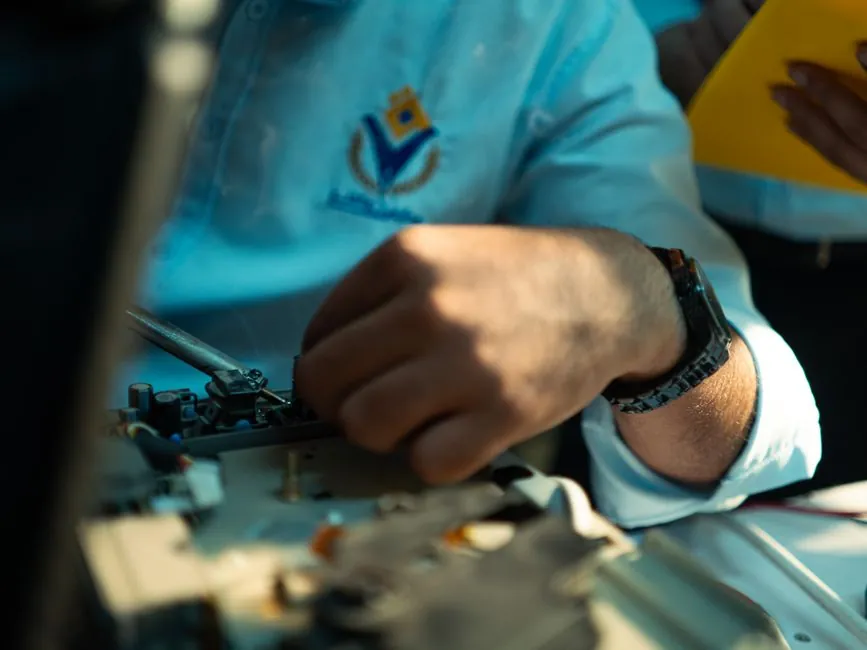
Spin Robotics states that automated cobot screwdriving reaches 99.9% accuracy in screw placement, with consistent torque and automatic error handling as the supporting performance trio [S1]. That number is a cell-level spec, not a robot spec: it is the combined result of the cobot arm, the screwdriving spindle, the feeder, the vision system, and the fixture that locates the part.
For automotive plants evaluating Universal Robots-based cells, the cobot is described as guiding the screwdriver to each fastening point with high positional accuracy, paired with screwdriving tools and feeders from ecosystem vendors [S2]. A common pairing is a Kolver K-DUCER controlled screwdriver on a UR arm, with Kolver explicitly marketing the bundle for repeatable and accurate assembly, including tightening data capture for full traceability [S3].
What "accuracy" actually means in a screwdriving cell
Accuracy in a screwdriving workstation is a stack of three numbers, not one: positional accuracy of the bit tip over the hole, angular accuracy of the bit to the hole axis, and torque accuracy on the joint. Cobots typically quote pose repeatability in the ±0.03 mm to ±0.1 mm range depending on payload and reach, but the bit tip repeatability is degraded by the mass, length, and stiffness of the screwdriving spindle mounted on the tool flange. [S1]
A second, less obvious variable is screw pickup. The screw has to be presented to the bit in a known X-Y-Z and known angle, otherwise each cycle starts with a different offset. Assembly Magazine captured the industry view clearly: "most cobots don't have the same level of precision and repeatability as SCARA or noncollaborative six-axis robots," which is why cell designers lean harder on fixtures and vision to compensate [S4].
A third variable is the joint itself. Torque accuracy on a correctly clamped joint typically sits in the ±2% to ±5% range for a current-generation DC transducer screwdriver, with angle-controlled strategies used for hard joints and slip-clutch tools reserved for soft joints where exact clamp force is non-critical [S3].
Selection criteria: cobot vs SCARA vs six-axis for screwdriving
Cobots win on three criteria: footprint (no safety cage, smaller inter-axis distance, can sit on a cart), redeployment time (often under one shift for a new SKU), and human-robot collaboration on mixed-model lines. SCARA wins on raw speed and on Z-axis stiffness for vertical driving. Standard six-axis articulated robots win on reach and payload for large parts such as automotive subframes. [S1]
Where cobots lose: high-torque joints above roughly 20-30 Nm where the arm stiffness and joint torque become the limiting factor; very high cycle rates above 30-40 picks per minute per spindle where SCARA dynamics dominate; and micro-fasteners below M1.6 where the bit concentricity and feeder precision, not the arm, dictate yield. The IFR noted 517,000 industrial robots installed in 2021, with automotive absorbing about 30% of that volume, the deployment base against which any new cell is benchmarked [S3].
For buyers comparing options on four decision criteria, the typical pattern is: (1) cell footprint, cobot < SCARA < six-axis; (2) cycle time per screw, SCARA < cobot < six-axis; (3) maximum joint torque, six-axis > cobot > SCARA; (4) redeployment hours for a new SKU, cobot < SCARA < six-axis. This four-axis comparison lets a plant engineer score cells against the actual mix of SKUs on the line.
Fixture, datum, and the 0.1 mm that decides yield
EVS International's June 2026 guidance reframes the cell around the fixture: a cobot screwdriving workstation should be judged by repeatable positioning and torque control, not by how quickly the robot moves between points [S7]. On that reading, the fixture datum surface and the locating pin scheme are doing more for end-of-line accuracy than the cobot model on the price list.
Three fixture rules hold across the cited material. First, use a 3-2-1 locate scheme on a single primary datum face so the part cannot shift under screw reaction torque, with clamp force applied to the largest available boss to resist the screw's axial pull-up. Second, the screw holes should sit within ±0.05 mm of their nominal position on a known repeatable fixture; if the part is plastic or thin-wall sheet metal, add a nest that backs the joint to stop strip-out. Third, the bit approach axis should be within ±1° of the hole axis, otherwise the bit will bell the hole mouth and the joint will read as a torque reject even though the screw is correctly torqued.
For optical correction, vision-guided hand-eye calibration on a fixed-mount camera can recover roughly 0.2-0.5 mm of part-to-part drift, but it does not save a poorly designed fixture. Vision finds where the hole is this cycle; the fixture decides whether that location is acceptable across all cycles.
Torque strategy and tightening data capture
The shift in the cited material is from "tighten to a torque" to "tighten to a torque-and-angle window with a captured trace." A controlled DC screwdriver such as the K-DUCER paired with a UR arm is explicitly framed as delivering repeatable and accurate assembly with full traceability of each tightening operation, which is the data backbone required for Industry 4.0 reporting and for warranty dispute defense [S3].
For a given joint, the practical torque window is set by the screw grade and the joint stiffness. A torque strategy on a hard joint is: ramp to a snug torque (roughly 30-50% of target), then angle-control from snug to final angle. On a soft joint, the simpler approach is a torque cut-off with a slow ramp to avoid overshoot. Either way, the controller should log final torque, final angle, cycle time, and a pass/fail flag per screw; that log is the audit trail a quality engineer needs when a downstream test rejects a subassembly.
For a working overview of how these tightening cells fit into the broader assembly-line fastening toolkit, see the locking-assembly reference, which covers prevailing-torque grades, washers, and joint-clamp behavior that any screwdriving cell must respect locking-assembly.
Where cobot screwdriving fits, and where it does not
Cobot screwdriving is the right tool when SKUs change frequently, batch sizes are measured in the hundreds rather than the hundreds of thousands, and the joint torque is under roughly 20 Nm, the band in which a typical cobot-mounted DC screwdriver delivers its best torque accuracy. [S4]
For higher-volume, higher-stakes fastening, dedicated construction-machinery and equipment assembly lines still rely on fixed multi-spindle units; for the kind of multi-attribute process data these cells generate, the engineering view on a pressure transmitter instrumentation bus shows the same pattern of digital capture replacing analog gauges, and the same need for the cell-level data to flow to a lighting-equipment and electric lamps status stack and an MES. For the QA side, torque and angle data on a rejected joint are checked with the same kind of checking and testing apparatus approach used elsewhere on the line.
Standards, traceability, and what to put in the RFQ
No single ISO or IEC standard governs the cobot screwdriving cell end-to-end, so the RFQ should pull in the relevant pieces. ISO 5393 covers pneumatic and electric power tool performance, VDI/VDE 2647 covers process capability of tightening processes on safety-relevant joints, and ISO 9001 traceability rules apply to the captured tightening data. On the robot side, ISO/TS 15066 defines the collaborative-mode power and force limiting that lets the cobot operate without a cage. None of these standards is optional in a regulated industry such as automotive or medical devices. [S1]
Two verifiable items to put in any cell RFQ. First, demand the bit-tip repeatability figure at the working payload, not the arm's pose repeatability at zero payload; the two numbers diverge once a screwdriving spindle is bolted to the flange. Second, demand a sample tightening-data log from the cell builder, in the format the plant's MES will consume, with one record per screw including torque, angle, and pass/fail. If the builder cannot produce that log on the demo cell, the production log will not be there either.
Where to track the next signal
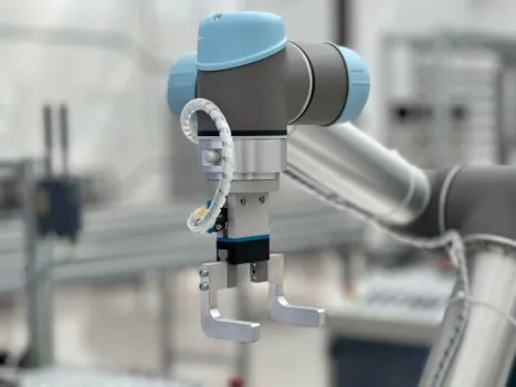
Two trackable items to watch. First, the migration of vision-guided screwdriving from fixed-mount cameras to on-arm cameras with hand-eye calibration, which is the next leg of accuracy recovery on parts that still cannot be fixtured to ±0.05 mm. Second, the convergence of tightening-cell data with plant-level cloud MES analytics, where the cobot cell becomes one more data source alongside the CMM robot loading cell and the stud-welding station, all reporting torque, angle, and pass/fail into the same schema for end-of-line warranty analytics. [S1]