Hospital slab-on-grade pours — operating theatres, MRI suites, pharmacy cleanrooms, and helipad decks — demand fiber-reinforced concrete to control plastic-shrinkage cracking and post-crack load transfer where welded wire mesh (WWM) cannot be relied on for tight joint spacings [S2][S3].
Three fiber families dominate current hospital specifications: hooked-end steel (CFS 100-2, CFS 150-5), macro-synthetic polypropylene (SikaFiber® macro, TenaBrix® macrofiber), and fibrillated polypropylene microfibers, each with distinct dosage, fire, and MRI-clarity trade-offs [S1][S2][S3].
Fiber Family Comparison: Steel vs Macro-Synthetic vs Micro
Hooked-end steel fibers such as CFS 100-2 at 20-40 kg/m³ deliver equivalent post-crack residual strength to WWF but allow joint spacing extended to roughly 30-40 m versus the 6 m typical of mesh-reinforced slab-on-grade, per Concrete Fiber Solutions product data [S1]. CFS 150-5 is UL Certified and listed for composite steel deck applications meeting ANSI/SDI C-2011, which is the relevant benchmark for steel-deck hospital floor pours [S1].
Macro-synthetic fibers — SikaFiber® macro and TenaBrix® twisted/synthetic macrofiber — dose at 3-9 kg/m³, are non-ferrous, and avoid the magnetic interference risk in MRI rooms; they are also chemically inert to the disinfectants and alcohol-based cleaners used in clinical flooring [S2][S3]. For pharmacy and cleanroom slabs where carbon-steel fibers can corrode and bleed at joints, macro-synthetic is the conservative pick.
Fibrillated microfibers (typically 0.6-0.9 kg/m³) address only plastic-shrinkage cracking in the first 24 hours; they do not replace structural reinforcement and are usually combined with rebar, mesh, or macro fibers in slabs that carry hospital equipment loads [S2][S3].
Decision Criteria Hospital Engineers Must Lock First
Lock the room function before picking a fiber: MRI suites and imaging rooms require non-magnetic, non-conductive reinforcement, which eliminates steel fibers regardless of dosage and pushes specification toward macro-synthetic or glass-fiber-reinforced polymer alternatives [S2].
Lock the slab thickness and joint layout next — extended-joint slab-on-grade designs above 30 m panel length only perform with steel or high-modulus macro fibers; micro fibers cannot hold an open joint [S1][S2].
Lock the floor covering system: urethane and methyl-methacrylate (MMA) toppings, common in operating theatres, demand a fiber that does not telegraph through the topping — macro-synthetic at the right aspect ratio (typically 60-90) resists protrusion better than cut-sheet steel fiber, which can puncture thin toppings [S2][S3].
Lock the admixture package and concrete admixture compatibility: polycarboxylate water reducers (PCE) extend workability for hospital slab placement windows but interact with macro-synthetic dosing — overdosing above manufacturer limits reduces slump retention and increases the risk of fiber balling during the concrete batching plant discharge.
Dosage, Mixing, and Placement Specifics
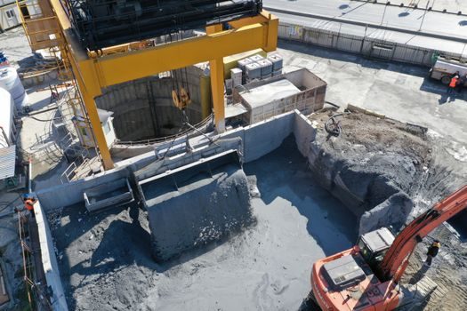
Steel-fiber dosing for hospital slabs is verified by ASTM C1116/C1116M fiber-reinforced concrete classification, with Type I (steel) fibers added at the concrete batching plant through a vibratory dosing conveyor to prevent clumping — drum mixing sequence must run at least 70 revolutions at mixing speed after fiber addition [S1].
Macro-synthetic fiber dosing follows SikaFiber® and TenaBrix® published data sheets recommending 3-9 kg/m³ for slab-on-grade with 15-20 cm thickness, dispensed via the same conveyor or pre-blended bag system; mixing sequence of 5-7 minutes at mixing speed is critical to disperse the fiber network without flotation [S2][S3].
Concrete placement uses a laser screed for hospital floor tolerances, with internal vibration by a concrete vibrator sized to the slab depth — 50 mm head for slabs under 200 mm, 75 mm head for thicker hospital basement or equipment-room pours.
Fire, Smoke, and Curing Requirements for Hospital Floors
Hospital floor assemblies in North America frequently must meet UL/ULC fire-resistance ratings; CFS 150-5 steel fibers carry UL certification for composite steel deck assemblies and are referenced against ANSI/SDI C-2011 for that reason [S1]. Macro-synthetic polypropylene fibers have a melt point near 160-165 °C and will melt out under fire exposure, so they are not interchangeable with steel where a 1- or 2-hour fire rating is mandated on the floor assembly [S2][S3].
Apply a concrete curing compound or wet burlene sheet immediately after final troweling; hospital slabs typically use a water-based acrylic curing compound compatible with subsequent urethane or MMA topping adhesion.
Joint cutting follows ACI 302.1R timing — typically within 6-12 hours of final finishing — using a concrete groove cutter set to a depth of 1/4 to 1/3 of the slab thickness; early-entry saws reduce raveling when macro-synthetic fibers are exposed at the cut face.
Where Steel Fibers Are the Wrong Call
Avoid steel fibers in any slab where future imaging equipment may be added or relocated, where epoxy or vinyl ester floor systems are post-applied over the slab, or where the structural drawings call for non-magnetic construction — fiber choice in these cases must be macro-synthetic or GFRP rebar with macro-synthetic [S2].
Avoid fibrillated microfibers alone for any hospital slab carrying vehicular or equipment loads (helipad, ambulance bay, MRI chiller room), where post-crack residual strength is required beyond the first 24 hours of plastic-shrinkage control [S2][S3].
Comparison Table: Three Fiber Types Against Hospital Spec Criteria
Steel (CFS 100-2 / CFS 150-5) vs Macro-Synthetic (SikaFiber® macro, TenaBrix®) vs Micro-PP — on residual strength, MRI safety, fire rating, and joint spacing: steel scores high on residual strength, low on MRI safety, high on fire rating, and high on joint extension; macro-synthetic scores medium-high on residual strength, high on MRI safety, low on fire rating, and medium on joint extension; micro-PP scores low on residual strength, high on MRI safety, low on fire rating, and low on joint extension [S1][S2][S3].
Limitations and Failure Modes

Fiber balling at the concrete batching plant discharge chute is the most common hospital-pour defect, traced to overdosing, insufficient mixing revolutions, or fibers added before the aggregate moisture is stabilized; the corrective step is a sieve check on the first batch [S1][S3].
Steel fiber protrusion above the floor surface — sometimes called "razor back" — can tear hospital-grade sheet vinyl and injure staff; mitigation is a hard-trowel finish with magnesium or composite floats, plus a 3 mm skim coat before floor covering installation [S1].
Macro-synthetic fiber slump loss is sharper than steel in hot weather; specify a concrete admixture retarding or workability-retaining PCE and confirm the truck has been re-mixed at the site before placement.
For data-center analog slabs the same family of decisions applies, and a side-by-side read of Concrete Fiber Selection for Data Center Slabs: 2026 Spec Map shows how anti-static and grounding requirements further rule out steel there — a constraint hospital MRI suites share.
Track these two signals on the next hospital project: confirm the EPD transparency for the chosen fiber (CFS publishes EPDs for its ProSlab system [S1]) and verify with the structural engineer that the fiber dosage line item on the mix design matches the dosage in the post-tension or rebar shop drawing before the first truck arrives. A third trackable item is the concrete curing compound compatibility letter from the topping manufacturer — that single document is what fails hospital floor inspections more often than the fiber choice itself.