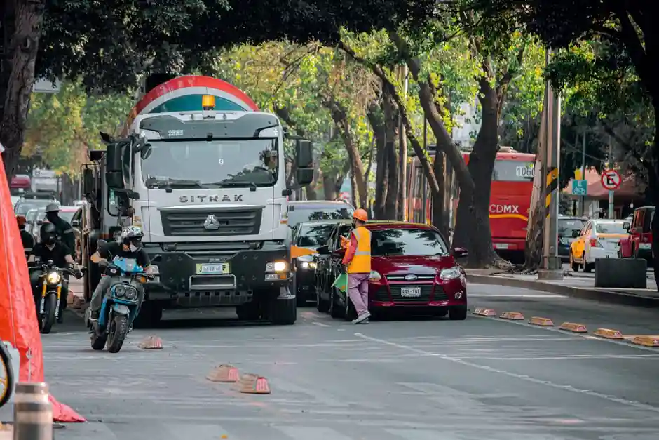
A concrete pump truck pre-start checklist dedicated to the engine cooling water loop must confirm radiator coolant level, belt and hose condition, fan operation, and thermostat function alongside the standard 36-check pre-pour protocol, because cooling failure under sustained pump load is one of the most common causes of mid-pour breakdowns [S1][S4].
The cooling loop sits at the intersection of the engine and hydraulics subsystems, and a coolant leak or restricted airflow can cascade into hydraulic overheating, ECU faults, and a $5,000 to $25,000+ per-incident pour abort, based on documented concrete pump failure cost ranges [S1]. Operators following ACPA-style hand-signal protocols and OSHA 29 CFR 1926 equipment inspection requirements must therefore treat the cooling circuit as a first-class inspection item, not a visual afterthought.
Cooling Loop Components and Verification Points
The engine cooling water loop on a concrete pump truck consists of the radiator, surge tank, water pump, thermostat, fan clutch or electric fan, coolant hoses, heater circuit, and any auxiliary oil-to-water coolers that feed the hydraulic reservoir. The standard concrete pump pre-start checklist contains 36 checks across seven sections, with engine and drive listed as section one, which is where the cooling circuit sits [S4]. A coolant level check on the dipstick-equivalent or sight glass, a visual scan of the radiator core for debris, and a confirmation that the pressure cap holds the rated system pressure are the three minimum items before engine start [S1][S3].
Operators should also verify that the coolant mixture meets the manufacturer freeze and boil protection specification, typically a 50/50 ethylene glycol to water blend, and that the coolant color is uniform without oily residue, which would indicate a head gasket or oil cooler leak. Field experience consistently ranks radiator fan failure, perished upper radiator hoses, and a stuck-open thermostat as the top three cooling-related no-start conditions on boom pump chassis.
How the Cooling Loop Interacts With the Hydraulic and Pump Systems
Concrete pump trucks place simultaneous thermal load on the diesel engine, the main hydraulic pump, and often a separate charge or cooler circuit for the S-tube and wear plate lubrication oil. The radiator therefore commonly cools two or three fluid streams: engine coolant, hydraulic return oil through an oil-to-water or oil-to-air cooler, and sometimes the charge air from the turbocharger. If the engine cooling loop is underspecified or partially restricted, hydraulic oil temperature climbs rapidly, which degrades seal life on the delivery cylinders and pistons [S5].
Operationally, operators are advised to monitor pumping pressure and system temperature simultaneously during the pour, because a hydraulic restriction or pipe blockage manifests as a heat rise upstream of the cooler before it shows up as a pressure spike on the concrete gauge. The pump truck's pre-operation checklist explicitly lists coolant level and hydraulic oil level as separate sight-glass items, reinforcing that these are coupled but distinct verification points [S3][S5]. This is also why a cooling water loop failure on a concrete pump truck is rarely an isolated repair; the same shift usually burns through seal kits and hydraulic filters as well.
Pre-Pour Walk Sequence: Engine Bay First, Then Coolant, Then Hydraulic Coupling
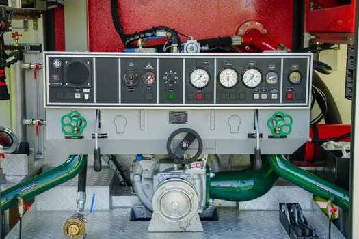
The sequence matters. Walk the engine bay with the platform down, fluid level checks first: engine oil, hydraulic fluid with platform down, radiator coolant at the surge tank, and fuel at a minimum one-quarter tank to support sustained pump operation [S1][S3]. Pull the dipstick, verify cell water levels on any serviceable batteries, and inspect belts for cracks, fraying, or slack before closing the bay. Air intake and exhaust system checks follow: confirm no leaks into the cab or platform area, and verify the exhaust after-treatment components are intact, since modern diesel pump trucks commonly pair DPF or SCR hardware with the cooling package.
With the engine bay closed, move to the cooling-specific items: top and bottom radiator hoses for softness or swelling, clamp torque, fan blade integrity, fan shroud condition, and any auxiliary hydraulic oil cooler lines that route through the radiator tank. A useful field rule is that if the upper hose is soft and the lower hose is hard immediately after a hot shutdown, the thermostat has likely failed open, and the loop will not reach operating temperature under load. This same thermostatic behavior is a known consideration in truck-mounted concrete pump chassis where the radiator is shared with the pump drive PTO gearbox cooler.
Comparison: Coolant Verification Methods on Boom, Line, and Mixer-Derived Pump Chassis
Three concrete pump configurations appear on jobsites, and each presents a different cooling loop inspection profile. A boom pump truck uses a large remotely-mounted radiator, often with a hydraulic-driven fan, which makes fan clutch engagement and hydraulic fan motor temperature the critical items. A trailer-mounted line pump uses a smaller engine radiator and frequently shares the chassis with a small diesel genset for the electric pump drive, so the cooling loop is paired with a generator coolant reservoir that must be checked separately. A mixer-derived pump chassis combines a concrete mixer truck drum drive with the pump hydraulic circuit, and the cooling loop is sized for combined thermal load, which raises the priority of the auxiliary oil cooler and the drum PTO temperature gauge. [S5]
On a four-criterion basis, the configurations compare as follows. Inspection time per shift: boom pump highest because of the hydraulic fan circuit, line pump medium because the cooler is small but the genset adds steps, mixer-derived pump highest when the drum is washing out. Coolant capacity: boom pump largest, typically 25 to 40 liters, line pump smallest at 8 to 15 liters, mixer-derived pump medium at 15 to 25 liters. Failure mode frequency: boom pump skewed to fan clutch and hose failures, line pump skewed to thermostat and water pump failures, mixer-derived pump skewed to auxiliary cooler fouling. Cost of a cooling-related pour abort: comparable across all three in the $5,000 to $25,000+ band cited in the field checklist reference, because the cost driver is concrete waste, not the component [S1].
Common Failure Modes and Field Rejection Criteria
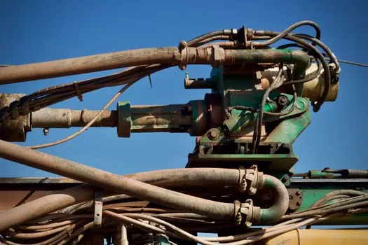
Reject the pump truck for pour if any of the following are present: coolant level below the minimum mark on the surge tank; visible coolant residue on the radiator core, hoses, or under the chassis; a soft or spongy upper radiator hose indicating internal collapse; a fan blade with chips, cracks, or missing tip weight; a fan shroud with broken or missing sections that allows air recirculation; a coolant cap that does not hold rated pressure on a hand pump test; a temperature gauge that pegs high or reads erratically during a 10-minute idle warmup; or any oily film in the surge tank or radiator neck [S1][S3][S5].
Acceptance criteria are equally explicit: coolant level at the full mark with the cap cold, fan and fan clutch or fan motor cycling normally, no audible water pump bearing noise, heater core supplying cabin heat at idle, and surge tank pressure holding with no visible weep at hose ends. Operators should also confirm the safety certification mark on the radiator cap and any pressure-vetted components, and check that the radiator cap rating matches the system pressure rating called out on the engine dataplate.
Standards, Documentation, and Audit Trail
Under the OSHA 29 CFR 1926 framework, equipment must be inspected before use on construction sites, and a documented pre-start record satisfies both the OSHA obligation and the DOT pre-trip DVIR requirement for on-road travel between job sites [S1]. In Australian WHS jurisdictions, concrete pumps are classified as plant under Chapter 5 of the WHS Regulations, and a pre-start inspection record is the standard method of meeting the PCBU's obligation to keep plant safe [S4]. Manufacturers recommend that operators follow the OEM operation and maintenance guide, including the lubrication chart for water pump bearings, and that they replace hoses on a time-based schedule, not just on visible wear, because peroxide-cured EPDM hoses degrade from the inside out [S5].
The audit trail should record coolant level, hose condition, fan operation, thermostat behavior on warmup, and any pressure-cap verification, dated and signed by the operator, and retained alongside the boom inspection and outrigger pad records. Where a pump truck is dispatched under a third-party safety certification scheme such as ACPA operator credentials or an equivalent national plant registration, the cooling loop items should be cross-referenced to the OEM maintenance schedule so an auditor can trace a failure to either an inspection gap or a maintenance interval gap. A practical safeguard for hazardous-area job sites is to coordinate the cooling loop inspection with the wider site hazardous-area classification, drawing on guidance such as Explosion-Proof vs Anti-Static: Spec-First Selection for Hazardous Areas when refueling or coolant handling occurs near classified zones.
Trackable Signals for the Next Inspection Cycle

Two signals are worth tracking shift over shift: the minutes to reach operating temperature on the engine gauge, and any coolant level drop on a non-consumed basis between identical duty cycles. A lengthening warmup time typically points to a stuck-open thermostat, while a coolant drop with no visible leak points to a head gasket, EGR cooler, or oil-to-water heat exchanger breach, and the truck should come out of service until a pressure test is performed. [S5]