
Electromechanical contactors combine a low-voltage control signal with high-current switching, commonly controlling motors, pumps, conveyors, lighting, and HVAC systems [S1].
The decisive comparison is mechanical simplicity against switching speed, noise, wear, and electrical-loss behavior, with coil voltage and contact configuration setting the operating limits [S1][S3].
How a Contactor Extends Control Across the Power Circuit
A contactor is an electrically operated power switch whose coil consumes control-circuit power while its main contacts open or close a separate load circuit [S1][S2]. In an electromechanical design, coil energization creates a magnetic field that moves an armature and closes normally open contacts, marked NO or 1a; normally closed contacts, marked NC or 1b, open when the coil is energized [S1].
The architecture separates three functional elements: the coil or electromagnet, the contact system, and the enclosure that protects the internal parts and insulation [S5].
That division makes a contactor more suitable than a conventional control relay for high-current loads.
Electromechanical and Solid-State Options Compared
Electromechanical contactors are generally less expensive and can handle high-current loads, but their moving contacts produce slower switching, mechanical wear, and audible buzzing or clicking [S1]. Solid-state contactors use semiconductors such as thyristors or triacs, removing moving parts and supporting faster switching, quieter operation, and longer service life [S1].
The two basic contactor designs are electromechanical and solid-state, with electromechanical contactors using an energized coil to open or close internal contacts [S1].
Electrical losses change the operating comparison. For AC operation, a conventional coil’s pull-in and drop-out performance can vary with supply voltage: a 220 V coil is convenient and economical but may have less electromagnetic holding force than a 380 V coil, particularly under voltage-drop conditions [S3].
Solid-state switching is not automatically the better engineering choice for every power circuit. Technology, voltage class, load current, short-circuit behavior, heat dissipation, and control compatibility must be matched to the application, while electromechanical contactors remain widely specified for robust, high-current switching [S1][S6].
Application Fit Determines the Better Contactor
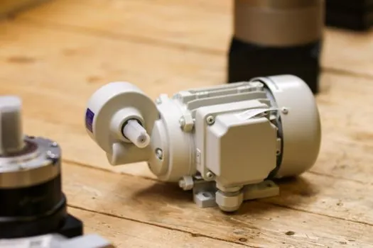
Electromechanical contactors are the practical choice for conventional motor starters, pumps, compressors, conveyor systems, industrial lighting, and HVAC equipment where a robust mechanical power switch and manageable acquisition cost matter [S1][S2][S5]. Their disadvantages are concentrated in slow operation, coil consumption, contact wear, audible noise, and a finite mechanical life [S1].
Solid-state contactors fit repeated or high-frequency switching where low acoustic output, fast response, and long component life outweigh semiconductor losses and switching-device cost [S1]. They are also relevant where solid-state control is integrated with other semiconductor-based automation equipment.
Special-purpose contactors address loads that conventional contacts may handle poorly. Lighting contactors are designed for high inrush current, while capacitor-switching contactors use damping resistors to limit inrush current in APFC panels [S2][S4]. Reversing contactors provide forward and reverse motion for conveyors, and thermal overload relays are used with contactors to protect motors and electrical systems against overheating [S1].
Contactor selection must therefore follow the load rather than a generic ampere rating. For a motor, the contactor installation guide for reliable commissioning is relevant where panel arrangement, wiring, and commissioning checks must preserve contact quality and repeatable operation.
Coil Voltage and Contact Configuration Set the Limits
Coil voltage is a system-compatibility decision, not a performance preference. A 220 V AC coil can use conventional residential or light-commercial control circuits without an added transformer, while a 380 V coil suits industrial control environments but can require additional power equipment and more complex installation [S3].
The 220 V option has lower coil power and a widely available electrical interface, but long cable runs can reduce coil voltage through voltage drop and impair operation [S3]. Common AC contactor coil voltages include 220 V and 380 V, with the 220 V option drawing less coil power and being convenient for residential and light-commercial applications [S3].
Coil selection should follow the control voltage rather than the load voltage, while power-circuit ratings must independently satisfy the load. MISUMI specifies selection by required voltage, maximum current including inrush, NO or NC logic, coil voltage, environmental protection, and regional safety compliance [S1]. A contactor with the correct load current can still fail if its coil supply, contact arrangement, or enclosure does not match the installation.
For conventional AC contactor families, operating efficiency can differ between AC and DC control, with DC control described as efficient and stable for consistent-current applications [S2]. This comparison remains application-dependent, so the control supply and required switching frequency should be evaluated before choosing between an industrial relay and a solid-state switching device.
Protection, Environment, and Maintenance Determine Reliability

A contactor does not replace motor protection. It is commonly used with overload relays and other protective devices, and thermal overload relays provide motor and system protection against overheating [S1][S4]. The contactor handles switching; the protective device handles specified fault conditions that the contactor itself should not be expected to interrupt.
Environmental selection requires at least three checks: the enclosure must provide suitable dust protection, it must provide suitable moisture protection, and the selected product must comply with safety requirements applicable to its region [S1]. These checks matter because coil condensation, dust accumulation, and contact contamination can reduce insulation performance or prevent reliable contact closure.
Mechanical contactors require planned inspection because moving parts wear over time [S1]. Maintenance should include checking contact condition, secure connections, coil behavior, enclosure integrity, and the operation of associated overload protection [S4]. Arc-free or vacuum-based designs address high-voltage, high-current interruption, but they are a distinct construction choice rather than a universal replacement for a standard contactor [S5].
Standards and regional compliance remain a mandatory part of the selection process, but the available research does not identify one universal standard covering every contactor rating, installation, and protection arrangement [S1]. The documented engineering sequence is to match voltage and current, verify contact configuration and coil supply, assess the environment, then confirm local compliance before energization.
Selection Checklist for Procurement and Engineering
A complete specification should record at least 7 decision fields: load voltage, maximum load current, contactor poles, NO/NC auxiliary contacts, coil voltage and AC or DC supply, switching frequency, and environmental protection [S1][S4]. For motor applications, add the overload-relay range and required reversing arrangement; for lighting, add the load’s inrush behavior; for capacitor switching, add the required inrush-limiting arrangement [S1][S2][S4].
Three practical comparison rules follow. Choose an electromechanical contactor when cost, robust high-current interruption, and a mechanical isolation gap dominate. Choose a solid-state contactor when fast operation, low acoustic output, high-frequency use, and long mechanical life dominate. Choose a special-purpose contactor when lighting or capacitor inrush exceeds what the standard model is intended to handle [S1][S2][S4].
Close the procurement process with traceable verification of contact ratings, coil data, auxiliary-contact configuration, enclosure rating, and regional compliance, then verify operation under the installed control voltage and load. The most trackable engineering signals are contact wear or erosion, abnormal coil noise, voltage-drop symptoms, and increased temperature at the power section.