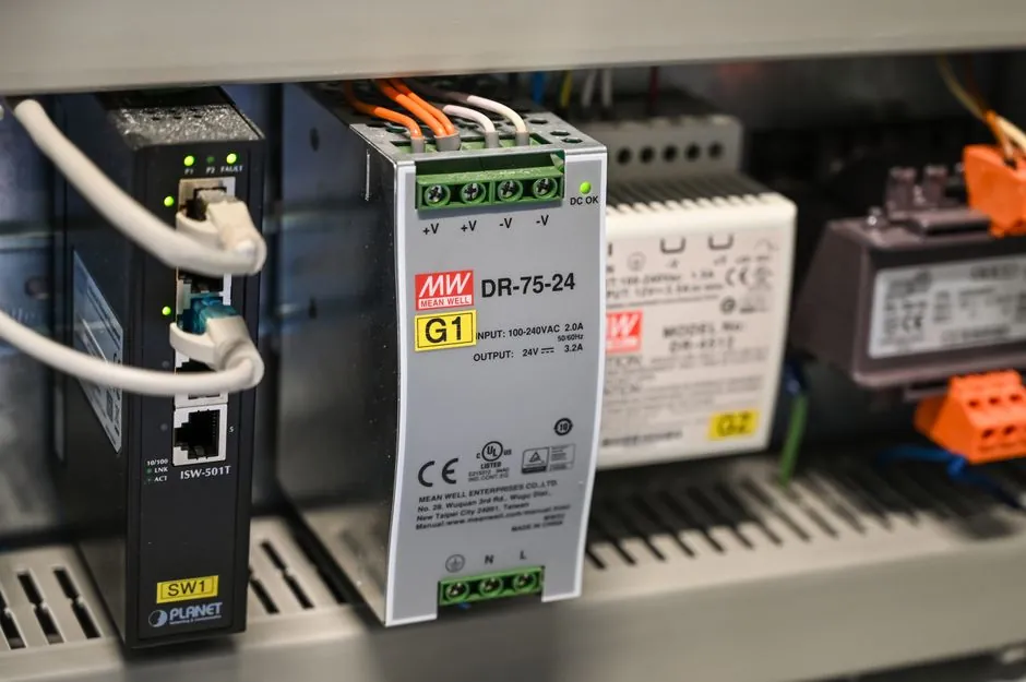
Transformer magnetizing inrush produces 8–15× rated current with a heavily DC-offset, sub-0.15 power factor waveform that persists 100–500 ms, which is a fundamentally different stress profile than motor starting current and the reason a same-ampere AC-3 contactor will weld when applied to a power transformer primary [S5].
Specifying engineers routinely treat transformer primary switching as if it were a motor load, then find contact erosion, nuisance trips, and welded poles within 50–2,000 duty cycles. The selection method is settled in IEC 60947-4-1 utilization category AC-6a and the older NEMA ICS 2 transformer-switching tables, but the field data behind those tables is what makes the difference between a 100 A and a 270 A contactor on a 30 kVA unit [S2][S5].
Why transformer inrush is not a motor-starting problem
Peak inrush for 50–2000 kVA distribution transformers typically reaches 8–15× I_rated, with worst-case measurements approaching 25× when residual flux polarity aligns with re-energization [S5]. Motor starting current is symmetrical, decays as the rotor accelerates, and presents natural current zeros for arc extinction, while transformer inrush is asymmetrical with a DC offset of 1.0–1.8× the AC peak and 5–25 cycle duration, which delays current zero and extends arc energy on contact separation [S5].
AC-3 contactors are tested at 0.35–0.45 power factor with inrush under 10 cycles. The same device at 0.15 power factor and 5–25 cycle duration accelerates contact erosion and has produced welding failures in field installations beyond roughly 50 duty cycles on transformer primary duty [S5]. Eaton's knowledge base therefore requires the AC-6a utilization category, with the formula Ie(AC-3) = (X/6) × Ie(transformer), where X is the inrush multiple, giving a 1.5–2.5× derating versus the motor-switching rating [S3].
IEC AC-6a vs NEMA transformer-switching tables
For IEC-rated contactors, the AC-6a method sets Ie ≥ X/6 × Ie(transformer): a 100 A transformer with 12× inrush therefore needs an AC-6a contactor rated at least 200 A, even though AC-3 might have allowed a 100 A device [S3]. The NEMA legacy approach from Sq-D Table 16.49 groups inrush into "<20×" and "20–40×" bins, which is why a NEMA Size 5 (270 A) contactor was recommended for a 30 kVA, 208 V (84 A) transformer primary, while a 100 A device would have looked sufficient on nameplate current alone [S2].
For general-purpose power transformers below 150 kVA, a common field shortcut is HP = 1.25 × kVA for NEMA HP-rated contactor selection, then check the calculated inrush current against the device rating [S2]. Vacuum contactors are the preferred technology above 400 A because the arc is contained in a sealed envelope, eliminating the atmospheric arc-extinction problem that plagues AC-3 air-break devices in this duty cycle [S5].
Design factors that swing the inrush multiple

Three variables dominate peak inrush: point-on-wave switching angle θ (θ = 0° produces worst case), residual flux polarity and magnitude B_r, and core saturation characteristics [S5]. Grain-oriented silicon steel, the dominant distribution-transformer core material, saturates at 1.9–2.0 T and retains 0.5–0.8 T of residual flux, while amorphous metal cores saturate lower at 1.5–1.6 T but retain less residual flux, producing inrush peaks 15–25% below an equivalent silicon-steel design [S5].
Smaller transformers generate proportionally higher inrush multipliers: a 50 kVA dry-type unit can hit 15× inrush while a 2,000 kVA oil-filled unit typically stays below 10×, an inverse relationship driven by per-unit magnetizing impedance and core cross-section [S5]. For dry-type units specifically, the air-cooled winding design and higher flux density operation often push the inrush multiple higher than oil-filled equivalents at the same kVA, which is a key spec-line item when sizing the upstream dry-type transformer feeder contactor.
Selection criteria and a worked comparison
Four decision criteria separate the three principal contactor families on transformer primary duty: inrush multiplier tolerance, contact life at AC-6a duty, coil VA and control transformer sizing, and switching frequency rating. Air-break AC-3 contactors derated per AC-6a (X/6) are the lowest-cost option for infrequent switching (≤1 close/open per hour) and have the widest installed base, but contact life drops sharply when the inrush multiple exceeds 10× or switching frequency exceeds 10 cycles/hour. Vacuum contactors carry AC-6a ratings natively, tolerate 15–25× inrush within their tested envelope, and are specified for 400 A and above where arc extinction in air becomes unreliable [S5].
A practical 30 kVA, 208 V three-phase comparison: transformer rated current ≈ 84 A, assumed inrush 12× (≈ 1,008 A peak); per AC-6a, Ie ≥ 12/6 × 84 = 168 A minimum, so a NEMA Size 4 (150 A HP-rated) is borderline while Size 5 (270 A) carries margin [S2][S3]. For a 500 kVA, 480 V unit with 10× inrush: I_rated ≈ 600 A, peak ≈ 6,000 A, AC-6a contactor ≥ 1,000 A, which puts the selection firmly in medium-voltage vacuum contactor territory or a 1,200 A air-break with capacitive make/break assistance [S5].
Limits, failure modes, and what the standards do not cover

Standard AC-6a tables assume worst-case point-on-wave (θ = 0°) and full residual flux retention. Control transformer VA, not just the primary contactor, is a common under-spec: a 270 A NEMA Size 5 contactor with four poles pulls roughly 170 VA inrush per Elliott Electric's Allen-Bradley 700-200 series data, which drives the upstream control transformer VA rating rather than the steady-state contactor coil burden of 56 VA [S6].
For low-voltage motor loads, contactor sizing for 3-phase resistive heater banks follows a near 1:1 amp rule, which contrasts sharply with the 1.5–2.5× derating the same hardware needs for a transformer primary, a difference that is the single most common spec error in panel builders' quotes. Failure modes the standards do not flag explicitly include contact welding after 50–2,000 cycles when AC-3 hardware is misapplied at 0.15 power factor, and nuisance tripping of the upstream MCCB whose instantaneous trip is set below the calculated 1,008 A peak on the 30 kVA example [S2][S5].
RFQ checklist and trackable signals
A spec-ready RFQ for a transformer primary contactor should include: transformer kVA, primary voltage, inrush multiple (or measured/calculated peak in kA), switching frequency in cycles/hour, AC-6a rating (not AC-3), coil VA at inrush and seal-in, and compatible switching power supply or control transformer VA for the coil circuit [S3][S5][S6]. On 2026-08-01, Industrial Monitor Direct published a NEMA ICS 2 sizing methodology with a 150 kVA oil-filled case study that walks the calculation line by line, a useful cross-check against the IEC AC-6a method when both standards are in play [S4].
Trackable signals over the next quarter: revisions to NEMA ICS 2 transformer-switching tables (the Sq-D Table 16.49 legacy reference was last reaffirmed in the 2014-09 cycle and has not been updated in the research material), and any IEC 60947-4-1 amendment touching AC-6a test currents at sub-0.2 power factor, since most vacuum contactor catalogs currently rate AC-6a only down to 0.2 power factor even though field inrush regularly runs lower [S5].