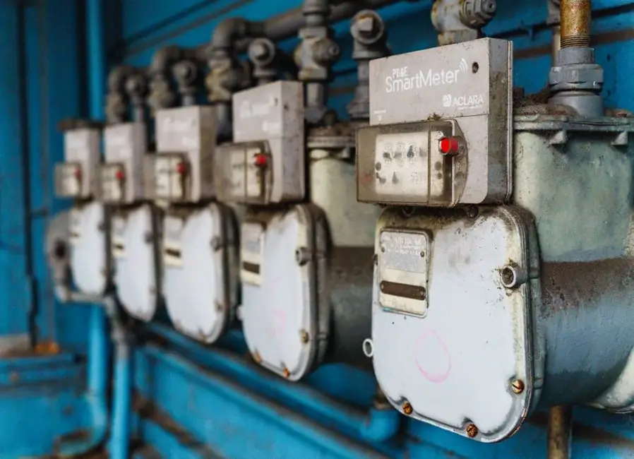
A control valve is a precision instrument sitting inside a piping system, and treating it as a line-of-pipe fittings is the single most common cause of premature failure: a control valve installed without an upstream strainer, vertical stem, or matched bypass will cavitate, leak past the seat, or fail its hydrostatic test within the first 12 months [S2].
This guide covers the working sequence used on chemical, HVAC and steam service, the failure modes that show up at commissioning, and the acceptance values an engineer can hand to QA. For a broader walk through how a control valve differs from a manually set isolation valve, the control valve encyclopedia entry is the right starting reference.
Pre-Lift Verification: Match Nameplate to Line Class Before the Valve Leaves the Crate
Before any lifting gear touches the valve, the nameplate must be cross-checked against the line class, the piping class, and the process data sheet; mismatches on size, pressure rating, body material, or end-connection style are the root cause of most field returns and the reason major handbooks dedicate their first installation chapter to this step [S1]. The four mandatory checks are: (1) valve size matches the line size and the calculated Cv/Kvs at the design duty point; (2) pressure rating (ASME Class 150/300/600 or PN16/40/64) is equal to or above the line rating, with margin for the hydrotest pressure; (3) body and trim material is compatible with the process fluid, temperature, and any NACE MR0175 requirement for sour service; (4) flanged ends share the same facing (RF, RTJ, FF) and bolt pattern as the mating flanges, and threaded or welded ends match the preparation on the pipe [S2].
Skipping any of these checks turns the installation into rework: a one-size mismatch on a flanged globe valve typically forces a 4-8 hour shutdown to re-machined spool pieces, and a body-material error in hydrofluoric or sour service is a safety incident, not a maintenance ticket. Engineers should also confirm the actuator model, spring range, signal type (pneumatic 3-15 psi, 4-20 mA, or fieldbus), and fail-safe action (air-to-close vs air-to-open) against the control loop schematic before mounting the actuator on the body.
Orientation, Support, and Piping Stress: The Three Rules That Prevent Stem Binding
Three orientation rules govern almost every control-valve installation: install on horizontal pipework with the stem vertical, align upstream and downstream flanges within 0.5-1.0 mm parallel offset, and support the piping on both sides so the valve body carries no deadweight from the line [S2]. The vertical-stem rule is not aesthetic; horizontal stems on globe valves collect condensate in the packing area on steam service and accelerate packing wear, while globe valves installed stem-down pocket debris on the stem and score the packing on the first thermal cycle. For ball and butterfly styles used as control elements on steam, manufacturers explicitly call out a stem-horizontal-to-piping rule to keep condensate away from the actuator housing, as documented in the Johnson Controls VG1000 Series installation instructions (Part No. 14-1201-5) [S4].
Piping stress is the second silent killer: a 50 mm misalignment on a DN150 flange at 1.6 MPa generates a bending moment that walks the valve body off its seat over a few hundred thermal cycles, and the symptom shows up as rising seat leakage rather than a sudden break. The fix is a pipe shoe or hanger within 1-2 pipe diameters of each flange face, plus a cold-spring alignment check before final bolt-up. For vertical runs, the valve should be supported independently of the pipe, not hung from it; the standard recommendation in the Emerson Control Valve Handbook is that the valve and the adjacent pipe spool be treated as a single supported assembly, with the supports sized for the valve's wet weight plus the water-fill weight during hydrotest [S1].
Strainers, Isolations, and Bypasses: The Supporting Cast That Makes the Loop Work
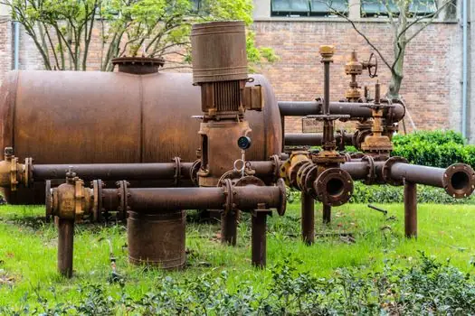
A control valve without an upstream strainer is a control valve with a scheduled failure date: dirt, weld spatter, and pipe scale lodge under the seat or in the cage windows, and the first sign is a step change in the valve characteristic or a stem that binds at 30-50% travel [S2]. Industry practice is a Y-type or basket strainer installed 3-5 pipe diameters upstream of the control valve, with a mesh size selected to retain particles larger than 5-10% of the seat orifice diameter; for severe service (e.g. boiler feedwater or refinery charge), a temporary start-up strainer with 20-mesh screen is fitted for the first 72 hours of operation and then swapped for the permanent unit once the line is clean. The strainer must have its own isolation valve so it can be cleaned without draining the control-valve manifold.
For maintenance access, full-bore ball or gate isolation valves are required on both sides of the control valve, sized at the same line size so that a hot change-out is possible without breaking the line; this is a hard rule in the THINKTANK commissioning practice and in the standard handbooks, because a DN80 control valve cannot be removed through a DN50 isolation on a live line [S2]. For plants that cannot shut down, a valved bypass must be fitted in parallel, ideally containing a second control valve (or at minimum a characterised throttling valve) with a matching Kvs so manual override does not disturb the loop; manual-only bypasses are widely discouraged because operators tend to leave them cracked open, defeating the control valve's authority in the loop [S2]. Where the loop drives a PLC setpoint, the bypass should also include a position transmitter or a hand-switch indicator so the controller can be put in manual without losing the process variable.
Hydrotest, Commissioning, and Stroke Checks: The Acceptance Numbers to Hand to QA
The pipework is normally pressure-tested at 1.5x the design pressure (or 1.25x for pneumatic service, per ASME B31.3), and the control valve body must be rated for that test pressure even if its working pressure is lower; the standard practice is to open the control valve to the fully open position during the line hydrotest so the seat is not loaded, and to fit a temporary spacer or a blind between the body and the actuator to protect the stem packing from the test pressure [S1][S2].
Commissioning the actuator and positioner follows three measurable checks: (1) a full-stroke travel check, end-to-end, with the positioner output signal moving from 4 mA (or 3 psi) to 20 mA (or 15 psi) and the mechanical travel matching the positioner feedback within 2% of full span; (2) a hysteresis test where the same input is approached from above and below, with the deviation between the two outputs logged and required to stay under 3% of full span; (3) a step-response test, where a 5% setpoint step produces a stable, non-oscillatory response within 2-3 dead-band-free cycles. For digital valve controllers (DVC6200-family and equivalents), these checks are automated through the diagnostic interface; for pneumatic positioners, a current-to-pressure (I/P) calibrator is the standard tool. The Emerson Control Valve Handbook treats these three checks as a single acceptance block that the QA inspector signs before the loop is handed over to operations [S1].
Common Failure Modes and What the Symptom Tells You About the Install
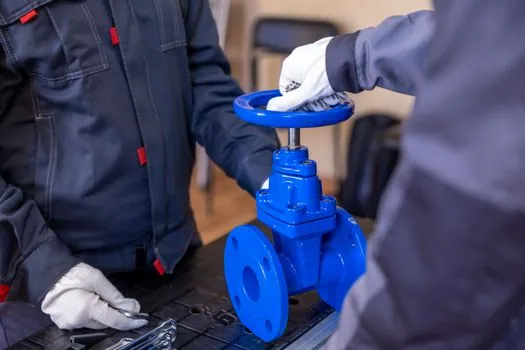
Symptom: rising seat leakage over the first 6 months. Root cause is almost always one of three installation errors: flanges mis-aligned (bending moment on the body), wrong direction of flow through a globe valve, or the line hydrotest performed with the valve closed (seat damaged by differential pressure). Corrective action is a full remove-and-reinstall with new gaskets and a documented cold-spring alignment; if the seat is visibly eroded, replace the seat ring rather than re-lapping. [S3]
Symptom: stem packing leak within the first 30 days. Cause is usually a horizontal-stem globe on steam service, packing that was never allowed to run-in, or a gland tightened before the first heat-up cycle. Corrective action is a controlled run-in (4-6 thermal cycles before final gland torque), not a packing replacement; if packing is already damaged, replace with the manufacturer's recommended graphite or PTFE set, torqued to the published value (typically 15-25 Nm on DN25-DN50 graphite packing) and re-checked after the first hot cycle. Symptom: valve hunting or oscillation in the loop. Cause is rarely the valve itself and almost always excessive deadband, an oversized valve (control authority below 30%), or a manual bypass left cracked open. The diagnostic test is to put the controller in manual and stroke the valve manually; if the oscillation stops in manual, the problem is in the loop tuning or the bypass, not the valve body.
Selection: When a Control Valve Is the Right Choice and When It Is Not
A control valve is the right specification when the loop needs continuous modulation, when the controlled variable (flow, pressure, temperature) must be held to within 1-2% of setpoint, or when the process fluid is hazardous enough that a fail-safe action (air-to-open, air-to-close, or spring-return) must be guaranteed on signal or air loss [S1][S3]. It is the wrong specification for pure on/off isolation (use a ball or gate valve, which are cheaper, full-bore, and bubble-tight at lower cost), for slurry service where the cage windows would plug (use a pinch or knife-gate valve), and for cryogenic LNG service where the extended bonnet would ice up faster than the loop can correct (use a cryogenic ball or globe with a specialised cold box).
For a decision-table view: globe valves deliver the best throttling range (typical rangeability 50:1) and are the default for steam, chemical dosing and refinery control loops; ball valves offer lower cost and higher Cv per line size but are typically limited to a rangeability of 30:1 unless a characterised ball or a V-notch ball is specified; butterfly valves are the lightest and cheapest DN300+ option but lose authority below 10% of rated Cv, making them poor choices for tight modulation. If the application is HVAC chilled-water or low-pressure steam with on/off or floating control, a forged-brass ball valve with an electric actuator (the VG1000 family, or equivalent) is the standard utility-grade solution, with the explicit instruction to mount the actuator at or above the pipe centerline and, on steam, with the stem horizontal to the piping [S4].
Standards, Sourcing, and When to Replace Instead of Repair
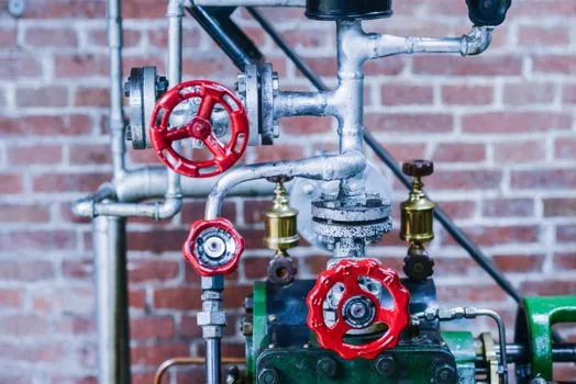
The two governing standards families for control valve installation and approval are the IEC 60534 series (industrial-process control valves, parts 1-9 covering nomenclature, capacity testing, and noise prediction) and the ASME B16.34 valve specification framework, both of which are referenced in the Emerson Control Valve Handbook and in the major manufacturer installation manuals [S1]. For hazardous-area service, ATEX 2014/34/EU and IECEx certification govern the actuator and positioner, while the body and trim compliance is covered by the pressure-equipment directive (2014/68/EU) and the ASME B31.3 process-piping code for the welded line.
Replace the valve rather than repair it when the body shows casting porosity on a hydrotest, when the seat is Class V or VI rated and the leakage has drifted outside the class limit (re-lapping will not recover tight-shutoff), or when the trim has been in continuous service past the published MTBF in a cavitating or high-erosion service. For buyers sourcing from China, the industrial valve sourcing map for 2026 lays out the verified-supplier gate and the spec documentation that should accompany any shipment. A field engineer's checkpoint after the loop is handed over: track the positioner output at 50% travel against the setpoint, log the trend for 48 hours, and require a deviation below 1% of span before the asset is released to operations.