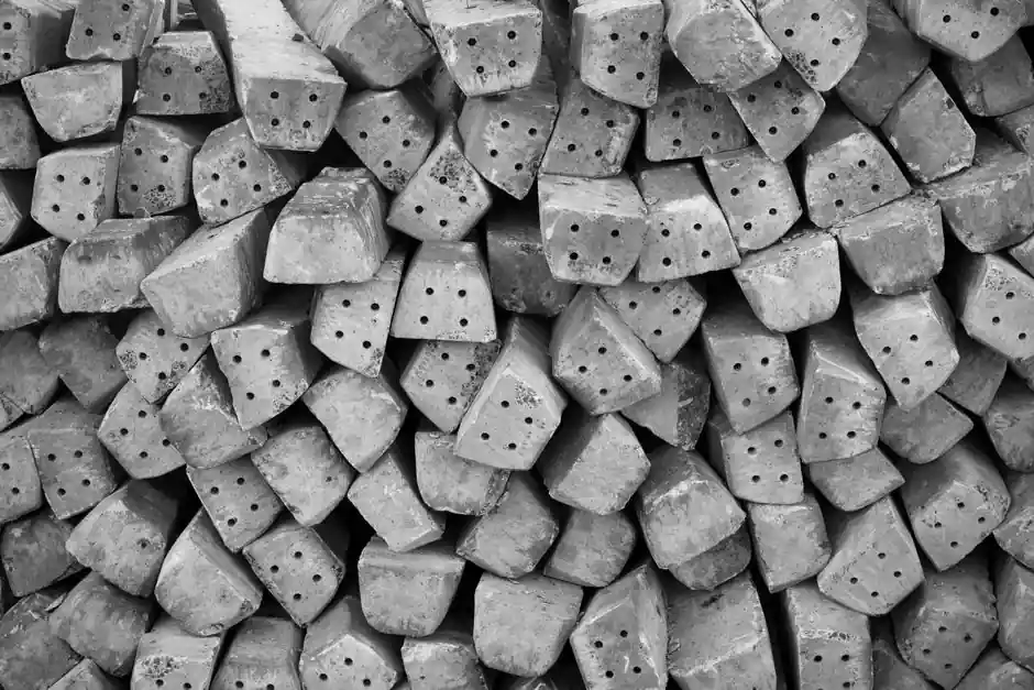
Sand molds are split horizontally into a cope (top half) and a drag (bottom half), with sand cores inserted between them to form internal cavities and a connected sprue, runner and gate network that delivers molten metal [S1][S2][S3].
The same four building blocks scale from a 2 kg aluminum bracket to a multi-ton steel housing, and they are the reason sand casting accounted for over 60% of all metal castings produced worldwide as of 2003, a share that has not been displaced by higher-pressure processes [S5].
Flask, cope and drag: the two halves that hold the sand
The cope and drag are the upper and lower halves of the casting flask, a frame that holds the molding sand during ramming and pouring, and they stay in use even when the process is run flaskless [S1][S2].
Flask bodies are normally aluminum, steel or wood, and an aligning system brings the cope back onto the drag along a defined parting line so the cavity registers cleanly [S2]. The cope typically carries the pouring basin, sprue and most of the riser volume because it sits above the cavity, while the drag carries the heavier core prints and the bulk of the runner system [S1][S4].
Maximum flask size is the practical ceiling on a job: one US green-sand shop quotes a 30 x 50 in flask and a 32 x 20 in maximum casting envelope from a pair of International Pin Lift cells, a useful benchmark for what "large part" means in manual cope and drag work [S4].
Cores: forming what the pattern cannot reach
Cores are preformed refractory inserts placed in the mold to displace sand where metal must not be, producing internal passages, undercuts and closed cavities that the cope and drag pattern alone cannot form [S2][S3][S5].
Core prints on the pattern register each core against the mold wall, and misalignment at this stage shows up directly as out-of-tolerance internal features [S3][S5]. Core production splits into hot-box and cold-box processes, with shell cores built as a thin sand shell against a heated core box for tighter dimensional control on precision jobs [S2][S3].
Chaplets, small clean and oil-free metal supports, hold large cores off the mold face so the core does not float or shift when the pour starts; misplaced chaplets are a common scrap cause because they leave a metallic inclusion on the cast surface [S1].
Gating system: pouring basin, sprue, runner, gate and riser
The gating system is the channel network that carries metal from the ladle into the cavity without eroding the sand, and it is built from a pouring basin, a vertical sprue, a horizontal runner, a choke, gates and ingates feeding the cavity, plus a skim bob and riser [S1][S2].
The sprue is straight and tapered so its height controls the velocity of the falling metal, while runners sit horizontal and distribute flow to multiple gates when the casting has more than one feed point [S2]. Risers, also called feed heads, act as reservoirs that feed liquid metal into the cavity as the casting shrinks during solidification, and they are the primary defense against shrinkage porosity [S1][S2][S5].
Vents are small openings that let gas and steam generated during pouring escape through the permeable sand or the risers, instead of being trapped inside the casting as blowholes [S2][S5].
Chills, wash coatings and shakeout: the supporting features
Chills are dense metal inserts placed in the mold to pull heat out of thick sections, raising local cooling rate and equalizing solidification so the riser can feed effectively [S1][S2]. They are used alongside risers on heavy bosses and flanges, not as a substitute for them.
Refractory washes, typically alumina or zircon based, are brushed or sprayed onto the mold and core faces to improve as-cast surface finish and reduce metal penetration into the sand grain [S3].
Shakeout is the step after solidification where the sand mold is broken away from the casting; in green-sand lines the sand is then reclaimed and the moisture and compactability are monitored in a dedicated sand lab to keep batch-to-batch behavior consistent [S2][S4].
Pattern, parting line and contraction allowance
The pattern is slightly larger than the finished part to compensate for contraction during solidification, and different scaled rules, one per alloy family, are used because each metal shrinks by a different amount [S2][S5].
The parting line is the horizontal split between cope and drag, and the pattern is designed so the part can be drawn cleanly out of the sand without damaging either half; for undercuts and internal features, the pattern carries core prints that index cores into the mold [S2][S5].
Pattern materials range from wood for short runs, to metal for high-volume work, to expanded polystyrene for lost-foam variants, and modern flow simulation (Magma and similar tools) is used to predict fill, solidification and defect locations before any sand is rammed [S3].
Selection: which sub-system matters most for a given part
For large, thick-sectioned steel or iron parts, the gating and risering system dominates the design, because shrinkage feeding and hot-tear control set the yield and the scrap rate; chills are added locally to balance cooling [S1][S5].
For complex internal geometry such as engine blocks, valve bodies and manifold passages, core design and core assembly dominate, and the choice between solid, hollow and shell cores is driven by collapsibility, strength and the need for venting [S3][S5].
For short-run prototype or low-volume work, the cope and drag tooling itself is the cheapest part of the package compared with die casting or investment tooling, which is why manual green-sand cope and drag is still standard for large aluminum castings up to about 32 x 20 in [S4].
Casting selection criteria line up across four axes: tooling cost (sand lowest, die casting highest), achievable part size (sand largest), internal feature complexity (core-dependent across all processes), and surface finish (sand granular, often preserved for aesthetic reasons on bronze and aluminum architectural parts) [S4][S5].
Common failure modes tied to each component
Shrinkage porosity traces to undersized or misplaced risers and to sections that solidify before the riser can feed them; chills and feed-aids are the standard fix [S1][S2].
Blowholes and gas defects trace to inadequate venting, low sand permeability, or blocked vents, and are reduced by adding vent paths at core assemblies and through the cope [S2][S3].
Core shift and broken cores trace to missing chaplets, weak core prints, or binder under-cure, and they show up as misplaced internal passages or sand inclusions on machined faces [S1][S3].
Pouring basin and sprue erosion trace to uncontrolled velocity at the sprue entrance, which is why sprues are tapered and why a pouring basin is used to settle the stream before it enters the downsprue [S1][S2].
Standards, certification and where the spec data lives
Most production sand casting shops operate under ISO 9001:2015 quality systems, with the certificate number, EAC code and certification date recorded on the foundry's quality page, which is the first document a buyer should request for any new source [S1].
For foundries supplying safety-relevant components, the same quality system plus customer-specific PPAP or casting qualification data governs acceptance, and the AQL sampling plan is set on the casting drawing rather than by the foundry [S2].
The reference model for the part itself is the pattern, and the reference model for the process is the gating diagram, both of which should be version-controlled alongside the simulation files used to design them [S3]. For shops working under tighter aerospace or rail schemes, additional Nadcap or customer-specific approvals sit on top of the ISO 9001 base, and these are the gating items for new part release.
For a deeper look at the mold and flask family as a whole, see the casting mold and sand casting mold reference pages, and for the tooling that supports the flask itself the mold base entry covers the standardized frame systems used on larger cells.
For the broader equipment context in which these cells run, the construction machinery and equipment reference page lists the kinds of gearbox housings, brackets and large castings that the cope and drag process still supplies today.
This topic is covered further in Time-series foundation models on industrial sensor data: where they pay off and where.