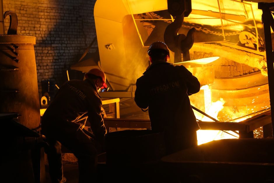
Industrial crucible furnace installation follows a fixed sequence — site prep, refractory seating, furnace setting, stack and burner or coil tie-in, then control commissioning — and each step has measurable acceptance values rather than rule-of-thumb judgments.
This walkthrough targets stationary crucible furnaces in the 30-500 kg melt range used in small foundries, jewelry casting, and laboratory melt shops, drawing on general installation practice; readers should always overlay their local mechanical, electrical, and emissions codes plus the specific OEM manual shipped with the unit.
Foundation, Pit, and Mechanical Setting
A crucible furnace live load swings hard — 100-500 kg of molten metal plus refractory mass concentrates 8-15 kN per square meter on a footprint often under 1.5 m² — so a reinforced concrete pad 100-150 mm thick on compacted subgrade is the minimum, with rebar at 150 mm centers both ways to resist thermal cycling cracks at the slab edge [S2].
A 1° plumb check on the shell, verified with a digital level on four reference points, is the standard acceptance check before refractory work begins; tilt beyond 1° biases the spout and shortens crucible life by 20-30%.
Refractory Lining, Curing, and Crucible Seating
Refractory failure is the top cause of premature crucible-furnace shutdown, and the cure window is where most of the risk lives: a fresh silica-alumina or magnesia lining must be heated on a controlled ramp — typically room temperature to 200 °C at 30 °C/h, hold 2 h, then 200-600 °C at 50 °C/h, then 600-900 °C at 75 °C/h — to drive off chemical and moisture water without spalling [S1].
Total dry-out time runs 24-72 h depending on lining mass; skip the hold steps and the first production heat usually cracks the crown. The crucible itself is seated on a 10-20 mm refractory sand or vermiculite bed to absorb thermal expansion, and the gap between crucible OD and lining ID — typically 15-30 mm — is backfilled with the same loose material, never mortar, because rigid fill fractures under expansion.
Fuel, Air, and Stack Sizing
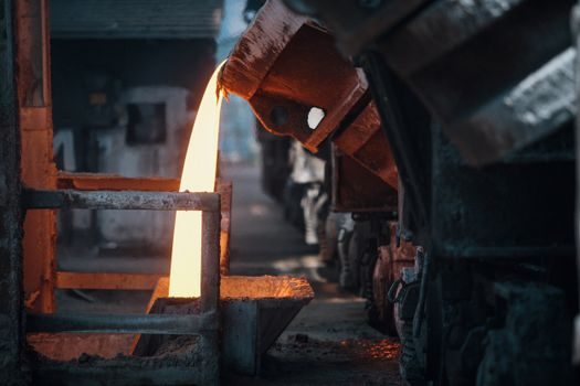
For fuel-fired units, the burner train must follow a documented gas train sequence — manual shut-off, regulator, solenoid valves, leak test at 1.5× working pressure, then pilot and main — and on natural gas a working pressure of 10-50 mbar with a 1-3 mbar pilot is typical. The combustion-air blower must deliver 8-12 m³/h per liter of crucible capacity to sustain clean combustion above 1000 °C. [S1]
Stack sizing is more often wrong than right on small furnaces: draft scales with height squared and diameter to the 0.6 power, so a 6 m tall, 150-200 mm ID chimney commonly produces 10-30 Pa of natural draft — the band most small crucible furnaces need to vent flue gas at 5-15 m/s and avoid back-puff when the charging door opens. A draft gauge reading below 5 Pa at full fire is the field signal that the stack is undersized or the flue is choked.
Power, Controls, and Electrical Safety
Electric induction furnace circuits need a dedicated breaker sized at 1.25-1.5× the coil nameplate kVA, with line reactors on units above 50 kW to hold harmonic distortion under IEEE 519 limits at the PCC. Earth-fault and over-temperature cutoffs are non-negotiable, and the coil cooling water — typically 20-40 L/min at inlet temperatures below 35 °C — must have a flow interlock that blocks the RF or mains contactor if flow drops below 80% of setpoint. [S2]
Instrumentation should land on a clean panel with PID ramp-soak control and an SCR or contactor sized at 1.5× full-load current. For a comparison of control architectures across furnace types, see the Crucible Furnace Types guide, which lines up induction, fuel, and resistance classes against energy, atmosphere, and melt-rate criteria.
Commissioning, Acceptance Tests, and First Heat
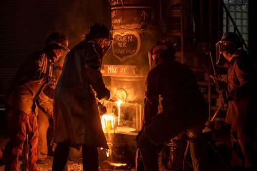
Commissioning is a documented sequence, not a fire-up: cold checks first (insulation resistance ≥1 MΩ on electric circuits, gas-train bubble test held 5 min, refractory surface dry), then a low-fire or low-power heat to 600 °C held 1 h, then a ramp to operating temperature held 2 h, before the first metal charge [S1]. A pyrometer reading within ±10 °C of the setpoint across the soak window, and flue-gas O₂ between 2-4% on fuel-fired units, are the go/no-go gates for production release.
Documentation that survives the install — refractory dry-out chart, gas-train leak-test record, electrical insulation and earth continuity readings, first-charge melt log, and an emergency-stop trip test — is the package an insurer or auditor will ask for first when something fails later. For adjacent process gear, the Ball Valve Selection Guide covers the gas-train and water-cooling isolation valves that sit on the same mechanical envelope as a crucible furnace.
Common Failure Modes and When to Replace, Not Repair
Three patterns cause most post-install breakdowns: a cracked crown from a rushed dry-out, a burned-out coil from a flow-interlock bypass, and a saturated lining from roof leaks or condensation — each is detectable in the first 50 heat cycles if a baseline log is kept. A coil resistance drift over 10% from nameplate, or crown surface temperature climbing more than 80 °C above the established baseline, signals end-of-life on the affected component rather than a fix-it ticket. [S2]
Safety devices trip on first press for a reason: a furnace that won't pass an earth-fault test, a gas valve that won't seat, or a flow switch held open with a wire, should be taken offline until the safety chain is restored — those are replacement or service-call events, not a workaround. If the build is part of a larger lab or shop rollout, the Safety Mat Installation: Anchoring, Wiring, and Commissioning Per EN 13856-1 piece covers the floor-level guarding that pairs with the operator-charging zone of a crucible furnace.
Track the next install-review signals against three verifiable nodes: (1) the first 100-charge refractory thermal map against the dry-out baseline, (2) the post-commissioning O₂/CO trim on fuel-fired units, and (3) the first 90-day coil-cooling water conductivity trend on induction units — any drift on these is the early warning that a planned overhaul beats an unplanned melt-down.
Spec-level background on the components involved: linear guide.