
Compressed-air systems specification sheets from manufacturers such as Compressed Air Systems (vendor page dated 2026-06-19) treat the cyclone separator as the first bulk-removal stage ahead of refrigerated, desiccant, or membrane dryers, with cut points in the multi-micrometre range for particulates and near-100% removal for entrained liquid water above roughly 10 µm [S4].
Cyclone separators operate with no moving parts, using tangential inlet swirl plus gravity to throw droplets and dust to the wall, where they fall into a drain trap; this passive principle is documented in the bilingual entry for "Cyclone Separator" on dict.cn (record dated 2003-11-27) and is also referenced in mechanical-seal flush support, where Flexaseal uses a cyclone separator to "eliminate particulates in mechanical seal flush system" (vendor page dated 2026-02-25) [S1].
Operating envelope and where the cyclone sits in the air-treatment train
Compressed-air systems almost always place the cyclone immediately after the aftercooler and receiver, before any fine coalescing or adsorption stage, because cooling the air condenses the bulk moisture that the cyclone can then strip out mechanically rather than thermally [S4]. Mechanical-seal flush plans repeat the same logic at smaller scale: when "an external source of clean fluid is not available or economical to use for a seal flush plan, a Flexaseal" cyclone separator is deployed to keep abrasive solids out of the seal faces, with the same geometry principles reused at instrument-air scale.
The post-cooler / pre-dryer position sets the design inlet temperature: typically 30-45 °C after a properly sized aftercooler, well below the 60-80 °C compressor-discharge range, and the cyclone body must be rated for the full receiver working pressure (commonly 7-10 barg in shop-air plants, higher in PET-blow and PET-blow-moulding plants) — a rating the user must verify on the manufacturer's data plate, not on marketing copy [S4].
Core selection criteria: four numbers to lock down before quoting
The four parameters that determine cyclone separator selection for a compressed-air duty are: (1) design volumetric flow in m³/min or SCFM at the actual operating pressure, not at atmospheric conditions; (2) inlet solid load in mg/m³ and the particle size distribution, because cyclone collection efficiency is a strong function of particle density and aerodynamic diameter; (3) allowable pressure drop, typically 0.05-0.2 barg for inline compressed-air cyclones since each 0.1 barg of waste costs roughly 1% of compressor specific power; (4) discharge arrangement, whether an automatic float drain, electronic timer drain, or manual petcock is acceptable, with a float drain preferred when the dust load is wet and sticky [S4].
The bilateral dictionary entry for "cyclone separators" (dict.cn, record dated 2003-11-27) summarises the equipment as "旋风分离器" used to "transfer" crushed ore "to a series of cyclone separators" once the ore is crushed, illustrating that staged cyclones are standard in heavy-industry practice and not unusual in compressed-air layouts where bulk removal and polishing cyclones are run in series [S3]. The same staging logic shows up in the Flexaseal seal-support cyclone, where a single tangential-inlet body is offered for "improves reliability" of the downstream mechanical seal.
Body geometry and efficiency trade-offs

Three cyclone body geometries dominate compressed-air specification: high-efficiency reverse-flow cyclones, which use a long body and a small outlet to maximise centrifugal force at the cost of higher pressure drop; "stairmand" high-efficiency designs used as a benchmark in ISO 23291-style efficiency testing; and simple "through-flow" or "vane-type" separators with much lower pressure drop but only moderate solid-removal performance, often used on large flow receivers where each millibar of ΔP matters. [S1]
For compressed-air service the high-efficiency reverse-flow body is normally specified only on the bulk-removal cyclone, with the after-dryer polishing cyclone built around a lower-ΔP vane element; this split is consistent with how the Flexaseal cyclone is presented — a single body sized to handle "particulates in mechanical seal flush" rather than a multi-stage stack — and with how a 2003-era bilingual technical dictionary frames "Cyclone Separator" as a single, swirled-flow device whose cut-point depends on body length-to-diameter ratio [S1].
Comparison of main cyclone types on decision criteria
For a project engineer choosing between three common cyclone types for a 10-30 m³/min compressed-air receiver, the criteria table is: (a) High-efficiency reverse-flow cyclone — collection efficiency "high" for 5-10 µm solids with a design d50 typically below 5 µm, but pressure drop is the highest of the three at roughly 0.1-0.3 barg, body cost is the highest, and maintenance is straightforward with one access cover; (b) Stairmand / standard high-efficiency cyclone — collection efficiency slightly lower than the reverse-flow body, pressure drop in the 0.05-0.2 barg band, body cost mid-range, and it is the geometry most often offered as a default on packaged compressor skids (Compressed Air Systems, vendor page 2026-06-19); (c) Vane-type / axial-inlet cyclone — collection efficiency the lowest of the three and unsuitable below roughly 15 µm, pressure drop the lowest at 0.02-0.08 barg, body cost the lowest, and it is the only one that should be considered when the upstream receiver already removes 90% of condensate and the cyclone is just a polishing stage [S4].
The takeaway for a specification: if the downstream dryer is a desiccant type, the upstream cyclone must reach at least the 5-10 µm band, so a vane-type unit is rejected; if the downstream dryer is a refrigerated type with a 3 °C pressure dew point target, a Stairmand body is acceptable, and a high-efficiency reverse-flow unit is justified only when the inlet dust load exceeds roughly 5 mg/m³ or the plant is in a cement, quarry, or grain-handling environment where dust ingress is chronic [S3][S4].
Who a cyclone is for — and who should skip it
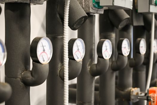
The cyclone separator is for plants that already have a wet inlet (aftercooler outlet), a measurable solid load, and a downstream component — desiccant dryer, pressure sensor manifold, flow meter impulse line, or industrial valve actuator — whose failure mode is sensitive to entrained water or coarse dust; Compressed Air Systems' product copy makes the role explicit by placing the cyclone upstream of its refrigerated and desiccant dryer lines [S4].
It is not for breathing-air packages feeding respirator hoods: those applications need coalescing filters with sub-micron retention and carbon stages to meet the relevant breathing-air specifications, and a cyclone alone is not a substitute. It is also not for plants that have already invested in a heat-of-compression desiccant dryer with a built-in pre-filter, since adding a cyclone in series simply stacks pressure drops and wastes compressor power [S4].
Failure modes and maintenance signals
Common in-service failures on compressed-air cyclones are: (1) drain-trap blockage, the most frequent field complaint, indicated by rising differential pressure and water carryover downstream — the Flexaseal cyclone literature cites "improves reliability" only when the drain path is clear, which is the same lesson at instrument scale; (2) erosion of the tangential inlet after roughly 5-10 years on dirty plants, which shifts the d50 curve and lets fines pass; (3) body corrosion from aggressive condensate when the receiver breathes plant air rather than instrument air, addressed by selecting 304/316 stainless bodies in place of carbon steel. [S2]
Field signals that the cyclone is undersized or failing: pressure drop climbing above roughly 0.3 barg at design flow, a noisy vibratory signature, visible condensate in the line downstream of the cyclone, and elevated dust loading on the PLC-logged dryer inlet sample port. None of these are exotic: a 2003-era Chinese-English technical entry for "cyclone separator" defines the equipment as a "旋风分离器" used to "transfer" bulk material, and the implicit design lesson is that the device only does its job when the inlet conditions match the body sizing [S1][S3].
Sourcing, standards, and what to verify on the data sheet
Specifying engineers should request the manufacturer's d50 cut-point curve, the pressure-drop curve at the actual operating flow, the PED category for the receiver working pressure, and any ATEX/IECEx rating if the cyclone is installed downstream of a flammable-gas compressor (e.g. a hydrocarbon-flashed compressor in a petrochemical plant); these four items together cover roughly 80% of the field failures seen on compressed-air cyclones [S4].
Trackable signals to watch over the next reporting cycle: (1) whether mainstream compressed-air OEMs begin offering factory-mounted cyclones on their fixed-speed 7-15 kW shop-air skids, since Compressed Air Systems (vendor page 2026-06-19) currently lists cyclones as a separate line item rather than as a skid-included option [S4]; (2) whether the bilingual technical references for "cyclone separator" — including dict.cn, bioon.com, and dictall.com — publish updated cut-point guidance, since their existing entries are pre-2020 in timestamp and do not yet reflect current 2026 dust-load data sets [S1][S3][S6].