External and internal gear pump families span roughly 0.6–132 m³/h (≈3.3–582 GPM) and discharge pressures from 2,000 psi hydraulic service down to sub-10 bar process duty, with the working envelope set by fluid viscosity, temperature and seal arrangement rather than by motor size [S1][S2].
Specifying one without locking those four inputs — viscosity, differential pressure, mounting style, and material compatibility — leads to accelerated wear, NPSH shortfall, or premature bearing failure; this guide walks through each gate with concrete data drawn from current OEM offerings.
Operating Envelope and Pump Family
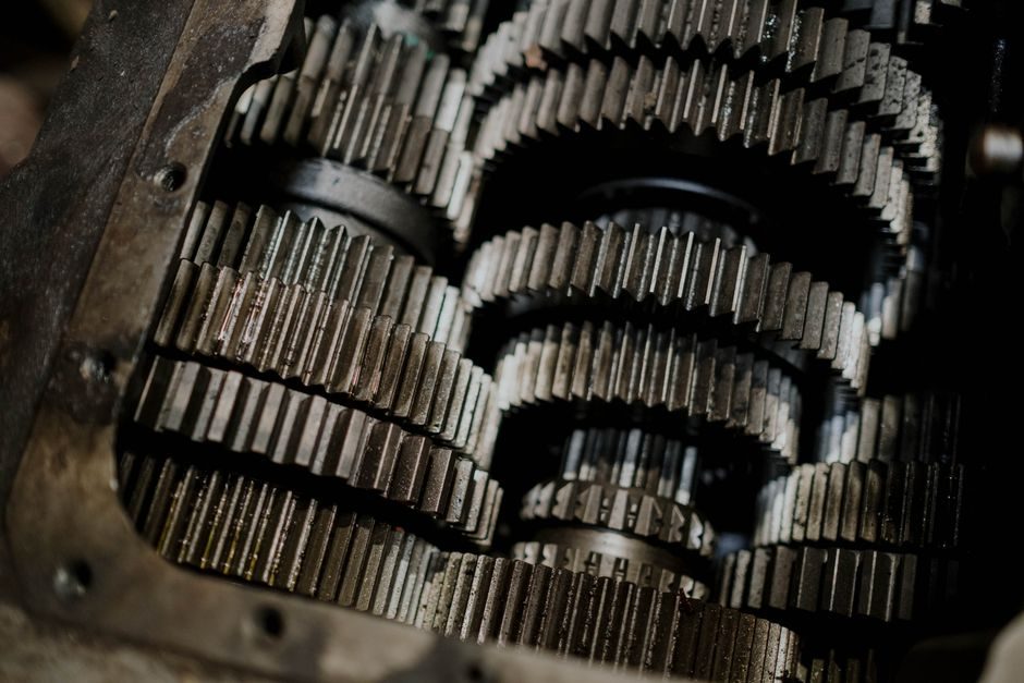
Industrial gear pumps divide into two principal geometries: external (spur, helical, double-helical) and internal (rotor-and-idler). External designs dominate the 0.6–132 m³/h range, with the Fluid Tech Systems FTR family sitting at the upper end at 132 m³/h (4,661.5 ft³/h) and the lower end at 0.6 m³/h (21.2 ft³/h), all on twin-external-meshing gears with double-helical tooth forms that cancel axial thrust [S2].
For high-pressure hydraulic and metering service, Clark’s 700 Series operates up to 2,000 psi (≈138 bar) at 1,725 RPM and 5.0 GPM, with cast-iron or ductile-iron bodies and lip-seal construction, making it a reference point for the upper pressure / lower flow corner of the external-gear envelope [S1]. Internal-gear builds such as HNP Mikrosysteme’s mzr-7205, mzr-4605 and mzr-2505 dosing series target low-flow, low-pulsation metering of water, paint and acids — a different corner entirely [S3].
Fluid Viscosity and Temperature Gates
Viscosity is the single hardest gate: a gear pump that runs cleanly on lube oil will seize within hours on a non-lubricating solvent. The FTR series accepts fluids up to 100,000 SSU (≈21,600 cSt) and fluid temperatures to 200 °C in its X-variants with independent bearing lubrication, while the lubricated needle-roller FTRN/FTRB models are limited to clean, self-lubricating media such as lube oil, gear oil, animal/fish oils, hydraulic oil, honey and vegetable oils [S2].
For non-lubricating or dirty service — crude oil, kerosene, paints, varnish, wood pulp — the same OEM routes the user to model FTRX, where the bearings are lubricated independently of the process fluid. Clark’s 700 Series solves the same problem by using the pumped liquid itself to circulate through anti-friction bearings, a layout that caps cleanliness and chemical compatibility at whatever passes through the seal area [S1]. The mzr-2961 internal-gear build extends the chemistry envelope further to acids and seawater, again confirming that material and lubrication strategy must be locked before flow and pressure are quoted [S3].
Pressure, Speed and Drive Coupling
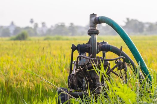
External gear pumps for viscous process service typically stop at 10 kg/cm² (≈9.81 bar) — the published FTR ceiling — because helical-tooth bending stress and shaft deflection become limiting above that point at industrial footprints [S2]. Hydraulic and metering gear pumps push the differential much higher: Clark’s 700 Series hits 2,000 psi at 1,725 RPM with flange or foot mounting and direct-drive coupling, suitable for skid-mounting next to a standard induction motor [S1].
Drive train selection matters as much as pressure rating. Direct-drive via a gear coupling or flexible spider coupling is standard; a misaligned coupling is the most common root cause of premature seal and bearing failure on gear-pump skids. In a helical gear reducer drive, the pump speed should be checked against the reducer’s output RPM band so that the pump is not run outside its specified speed window. For very low-flow dosing, mzr-series internal-gear pumps are typically paired with a small servo or stepper drive rather than an AC motor.
Materials, Mounting and Seal Architecture
Material selection is driven by fluid chemistry, temperature and abrasion risk. The Doright carbon-black feeding pump uses high-heat-resistant stainless steel castings for rotor, body and end cover, with extra thickness added at the high-wear zones, and is delivered skid-mounted for direct drop-in installation on a granulator line [S3]. Clark supplies 700 Series bodies in cast iron as standard and ductile iron as an upgrade for higher-pressure or shock-load duty, with lip seals as the baseline [S1].
For hygienic or food-grade duty — honey, vegetable oil, sugar, chocolate — a three-piece construction with easily cleanable internals is the design pattern of choice, and the FTR’s three-piece body is explicitly marketed for that maintainability [S2]. For abrasive or corrosive fluids, hard-facing, duplex stainless, or alloy-20 internals are typical upgrades; the OEM data in this guide does not name a specific alloy, so that decision should be made against the fluid’s chloride, pH and solids-loading profile.
Selection Criteria Compared
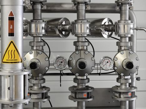
The decision comes down to four axes: flow rate, differential pressure, fluid viscosity/lubricity, and chemistry. The table below lines the three reference models up against those axes using the OEM-published numbers only — no extrapolated data. [S1]
Clark 700 Series targets 0.08–0.32 m³/h (5 GPM) at 138 bar (2,000 psi) on clean lubricating liquids in cast/ductile iron, flange or foot mounted, direct drive [S1]. Fluid Tech Systems FTR spans 0.6–132 m³/h at ≤10 kg/cm² (≈9.81 bar) on fluids up to 100,000 SSU and 200 °C, three-piece body, foot mounted, with model variants FTRN/FTRB for self-lubricating fluids and FTRX for dirty or non-lubricating media [S2]. Doright’s carbon-black pump is a stainless-steel, skid-mounted, two-rotor positive-displacement unit for abrasive granules and process control, with a flow rate decoupled from bed height and pressure fluctuation — a behavioural rather than a published number [S3]. A typical hydraulic / lube oil skid falls in the 700 Series corner; a molasses, honey or crude transfer line falls in the FTR corner; an abrasive or corrosive slurry line belongs with a Doright or industrial gear pump build.
Use Cases, Limits and Failure Modes
External gear pumps tolerate viscous and even non-Newtonian fluids, run at modest speeds, deliver pulseless flow proportional to RPM, and self-prime on most liquids — but they will not run dry, cannot handle large solids, and lose volumetric efficiency as differential pressure rises because internal leakage past the tooth tips scales with pressure. The 10 kg/cm² FTR ceiling is a direct consequence of that leakage-vs-efficiency trade-off [S2].
Hydraulic-duty builds such as the 700 Series are pressure-rated but flow-limited; they are also unforgiving on contamination because the lip seal and anti-friction bearings share the same fluid path [S1]. Skid-mounted abrasive-duty pumps like Doright’s solve solids-handling by adding rotor self-wiping at the contact point, which keeps the delivery volume stable even when bed height varies — a feature worth specifying on any feeder application where downstream throughput depends on stable mass flow [S3]. For a broader perspective on how pump choice ties into a skid’s linear guide alignment or crossed-roller guide staging for actuator-equipped metering skids, the mechanical layout of the skid will constrain coupling tolerances and shaft alignment.
Sourcing, Standards and Verification

Public OEM data on DirectIndustry (Clark, Fluid Tech Systems, Doright) is the most reliable first stop for flow, pressure, viscosity and material envelopes [S1][S2][S3]. For hydraulic and lube-oil service, the API 676 common API standard for positive-displacement pumps is the reference framework for acceptance testing, though OEM datasheets are the binding spec for the exact unit. For hygienic or food-contact service, 3-A, EHEDG or equivalent regional standards govern cleanability, and a three-piece body such as the FTR’s should be confirmed against the relevant document before purchase [S2].
Two trackable signals to watch before issuing a PO: (1) confirm the OEM’s published viscosity ceiling in cSt or SSU matches the actual fluid at the operating temperature, not at 40 °C reference; (2) confirm the published speed and pressure ratings with a real nameplate on the build, since published maxima are often de-rated for continuous duty. The same decision logic that drives a control valve selection guide on Cv and SIL applies here — lock the operating envelope first, then match the hardware.