
Dark-board philosophy on operator panels is the direct industrial translation of the cockpit "quiet/dark" rule: a pilot light remains unlit during normal operation and only illuminates when the controlled system enters a non-normal state [S1]. The principle is operational, not aesthetic, and the engineering pay-off is a panel that an operator can scan in under a second for the one beacon that actually matters [S1].
The trade-off is well documented on legacy annunciator panels: a dark lamp cannot be distinguished from a failed lamp, which is why dark-board designs require either push-to-test circuits, dual-LED modules, or a brightness-sensing feedback path so a dead indicator can self-report [S2][S7]. The 22 mm Ø22.5 mm cut-out remains the dominant industrial footprint, with LED elements running 6 V to 220 V AC/DC and dropping steady-state consumption from roughly 1.5-2.5 W (incandescent) to 0.5-1.0 W per indicator [S3].
Definition and Scope of Dark-Board Operation
Dark-board design is formally defined in avionics as the quiet/dark philosophy: a screen or annunciator stays black until a system condition warrants notifying the pilot, with a warning annunciator that only illuminates during a failure condition [S1]. On a discrete-assembly control panel, the equivalent is a 30-lamp annunciator where 29 lamps are off during steady-state, and only the fault channel lights [S1][S2]. The reader gets the same information density, but the visual noise floor collapses, which is the entire point of the topology [S1].
Scope is constrained to the panel-HMI layer; dark-board does not address back-of-panel wiring, contact blocks, or PLC scan logic, and the philosophy is independent of whether the lamp source is LED, neon, or incandescent, although LED dominates new builds at roughly 100,000 h service life and 0.5-1.0 W per indicator versus 1.5-2.5 W for the legacy filament pattern [S2][S3]. For a 30-lamp annunciator the difference is on the order of 30-60 W continuous dissipation, which matters on battery-backed control circuits and on long panels where thermal load adds up [S3].
Selection Criteria: When Dark-Board Fits and When It Fails
Dark-board fits discrete-state processes where each channel is binary, the population of indicators is large (typically >20), and operator scan time is the bottleneck, exactly the use-case for annunciators, machine-tool status panels, and substation mimic panels [S1][S2]. It fails on continuous-trend processes where the operator must see magnitude (level, flow, temperature), on safety-shower or evacuation-route signage that must be visible at all times, and on any channel where a lit condition is the normal state (a green "system-on" lamp, by convention, defeats the philosophy) [S1][S2][S6].
Color convention is the second gate: the industry standard is green for "system on / ready", red for "fault / stop / emergency", amber-yellow for "warning / transition", with white and blue reserved for call attention and function-specific roles [S2][S6]. On a dark-board, red and amber carry the load, while green is often eliminated or moved to a single master-power indicator to keep the panel visually quiet during normal operation [S2][S6]. Voltage convention follows the same path: 24 V DC for solid-state PLC outputs and 120 V AC for relay-coil legacy, with multi-voltage universal LED blocks now accepting 6 V to 220 V AC/DC without a step-down transformer, which removes a whole class of 24 V-only mis-wiring failures on retrofit jobs [S3].
Comparison: Dark-Board vs Always-On Indicator Strategies

The three legitimate strategies on a 22 mm panel footprint line up against four decision criteria: operator scan time, lamp-out detection, energy and thermal load, and wiring complexity [S1][S2][S3]. Dark-board wins on scan time and energy, loses on lamp-out detection unless mitigated, and is neutral on wiring because the same 1NO-1NC contact block pattern carries all three options [S3].
Always-on (green-master) is the legacy pattern: simple, but the operator must distinguish 29 green lamps from 29 dark lamps, which is the same scan problem in reverse, and a single failed green lamp is invisible until the next maintenance walk-around [S1][S2]. Dark-board with push-to-test inverts the failure mode: a dead indicator is only found during the test cycle, but a periodic push-to-test routine or PLC-driven lamp-test input closes the gap, and the panel stays quiet between tests [S2]. Dark-board with brightness-sensor feedback, as implemented in the JUNG AL 1539-O D LNW floor pilot light with integrated brightness sensor at 0.3 W standby and 0.5 W ON, self-reports a failed LED without operator action and is the closest engineering answer to the original cockpit complaint that a dark switch position is ambiguous [S1][S7]. For adjacent HMI hardware trade-offs, the pushbutton pilot light sizing selection map covers the contact-block and cut-out choices that sit underneath any of these three strategies.
Lamp-Out Detection and Push-to-Test Engineering
The single biggest technical risk in dark-board is a failed lamp masquerading as a healthy dark state, and the mitigation is hardware, not procedure [S1][S2]. Push-to-test pilot lights integrate a test button that operators press to verify the lamp element is functional, and the feature is specified for safety-critical systems where regular checks are necessary to confirm the pilot light's function [S2]. The implementation can be a mechanical momentary contact in parallel with the indicator, or a PLC-driven lamp-test output that energises all 30 annunciator lamps simultaneously for a one-second walk-around check, which is the pattern carried over from the cockpit annunciator panel [S1][S2].
Multi-colour and multi-voltage modules complicate the test path because a single dual-LED module that glows green for normal and red for fault has two semiconductor chains, and a partial failure (one chain open) is invisible during a lamp-test that only exercises one colour [S2]. Schneider's Harmony XB5 ZB5CV013 head for pilot light, square white, 22 mm, plain lens, universal LED, accepts the same body across green, red, white, and yellow caps and is documented as compatible with the universal LED blocks, which keeps the lamp-test path consistent across colour channels and reduces the spares inventory for a dark-board retrofit [S5]. The wider indicator-circuit context, including lamp-base standards (BA9s, BA15d, wedge) and life ratings, sits on the panel indicator reference page, which is where the cross-check between LED retrofit bulbs and legacy sockets lives.
Real Use Cases on Operator Panels
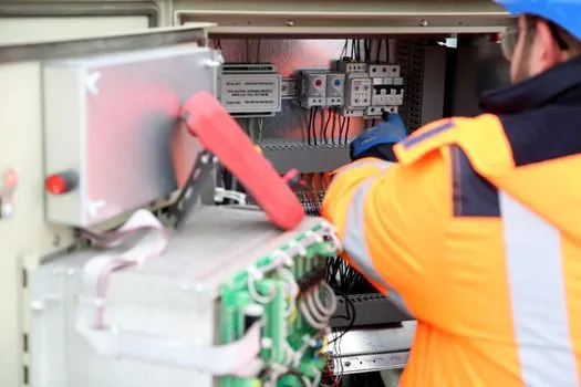
Use case one: a 30-station discrete-assembly line where each station has a single red fault lamp, normally dark, and the line controller lights the offending station's lamp within 200 ms of a station-stop event. The operator sees one red dot out of 30, walks to it, and clears the fault; scan time is sub-second and the panel never lights during normal production [S1][S2]. This is the canonical dark-board application and the one the cockpit philosophy was written for [S1].
Use case two: a substation mimic panel where each circuit breaker carries a red closed-indicator and a green open-indicator; under dark-board rules, only the red lamps are wired and a breaker in the open state shows as a dark position, which matches the cockpit pattern but requires a separate breaker-position transmitter or auxiliary contact to validate the dark state [S1][S2]. Use case three: a relay-status panel with a 24 V DC or 120 V AC pilot light per output, where the colour follows the green-red-amber convention and the dark state means "relay de-energised, no call to action" [S2][S6]. Each case is a translation of the same quiet/dark rule into a different process state, and the engineering decision is the same: which channels are dark by design, and which channels must be lit at all times [S1].
Limitations, Failure Modes, and Sourcing
Dark-board fails when the operator is expected to confirm a healthy state visually, when the panel is in a high-vibration or dirty environment where a failed LED cannot be distinguished from a working one, or when the control logic is not deterministic enough to guarantee that a dark lamp really means "normal" [S1][S2]. Mitigations are: (a) a periodic lamp-test routine hard-wired into the PLC scan, (b) brightness-sensor feedback that flags a sub-luminous LED, or (c) a redundant dual-LED module with two parallel semiconductor chains, accepting the cost penalty for the safety-critical channel [S2][S7]. Sourcing follows the standard 22 mm panel ecosystem: Schneider Harmony XB5, Allen-Bradley 800GP1EX, Clipsal, Tend, Teknic, and the compact Ø16 mm TN16/TT16/T16 series for dense instrumentation front-plates where the 22.5 mm cut-out will not fit [S3][S5].
Standards and zoning constraints apply unchanged from any pilot-light installation: IEC 60529 (ingress, referenced as IEC 144 in some vendor literature) sets the IP65/IP66/IP67 washdown grades; the IEC 60079-10-1 zoning model governs Zone 1 and Zone 2 hazardous-area pilot-light selection with matching gas-group certification; contact blocks on the SZB022-BP family cover 1NO, 1NC, 1NO-1NC, 2NO, and 2NC, and the flat illuminated type accepts three contacts per layer for six contacts total per operator [S3]. The next trackable signal is the IEC/TR 62635 recyclability common-standard publication flagged for end of 2026 in the Schneider ZB5CV013 environmental data, which will set the comparability baseline for end-of-life take-back across the 22 mm Harmony XB5 family [S5].
Component reference pages worth checking: insulation board.
For related coverage, see Diesel vs Electric HPU for Remote Wellsites: 2026 Selection Guide.