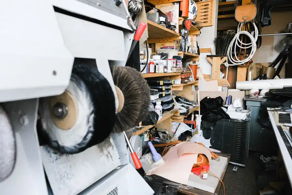
Deburring machines remove the small ridges, protrusions, and slag that machining processes leave on metal workpieces, converting sharp rollover, Poisson, and breakout burrs into smooth, functional edges [S1].
The four dominant working principles in industrial use are mechanical abrasion (belt, brush, or rotary tool), mass-finishing (vibratory or centrifugal barrel), thermal deburring (combustive gas burn-off), and electrochemical deburring (anodic dissolution in an electrolyte) [S1][S2][S4][S5][S6].
Mechanical Deburring: Abrasive Belt and Brush Heads
Mechanical deburring relies on directly driven deburring tools such as abrasive belts, brushes, milling cutters, polishing heads, and electroplated tools contacting the workpiece [S2]. A wide-belt abrasive rotates around a drum against the direction of material feed to shear off edge burrs, and a counter-rotating barrel brush then softens any secondary burr left lying flat on the leading edge [S3]. Single-head machines handle simple geometries, while multi-head machines with two or more stations are used where both edge radius and surface finish must be controlled in one pass [S3].
Mechanical systems scale from hand-fed bench units to fully automatic robot cells; KADIA cites cylinder block, cylinder head, crankshaft, steering rack, and drive shaft applications as typical engine-manufacturing workloads processed wet or dry [S2]. Because no chemical or thermal energy is applied, dimensional stability and base-material microstructure are preserved, which matters for heat-treated or case-hardened components [S2].
Mass-Finishing: Vibratory and Centrifugal Barrel Tumbling
Vibratory deburring machines work by filling a large chamber with abrasive media such as steel, ceramic, plastic, and occasionally glass or organic material, then vibrating the chamber so the media slides across parts and burnishes edges [S5]. Cycle times for vibratory bowls typically run 15-60 minutes per batch, and the process handles loose burrs effectively but struggles with fixed, heavy burrs because the impact energy per particle is limited [S5].
Centrifugal barrel tumblers accelerate the process by mounting smaller baskets on the edges of a large rotating wheel, using G-forces several times gravity to push media against parts [S4]. Higher G-force loading shortens cycle time versus vibratory bowls and produces a more consistent edge radius on small, high-volume parts, at the cost of higher capital cost and limited batch size per loading [S4].
Thermal Energy Deburring
Thermal deburring uses a combustible gas mixture (typically hydrogen and oxygen, or methane and oxygen) ignited in a sealed chamber to briefly raise the part temperature to roughly 3,000 °C, scalding off thin burrs and slag while leaving the bulk material largely unaffected [S1]. Because flame and combustion products reach into cracks, cross-holes, and intersecting passages that brushes cannot, thermal deburring is the standard choice for complex hydraulic manifolds, valve bodies, and pressed-together assemblies with internal burrs [S1].
The same access advantage limits the process to parts made of metals that can tolerate a rapid thermal cycle without distortion; thin-wall aluminum and copper components often need fixturing or shielding, and any polymer or elastomer seal must be removed before processing [S1].
Electrochemical Deburring (ECD)
Electrochemical deburring removes material by controlled anodic dissolution in an electrolyte, typically a salt or glycol solution, with the workpiece as the anode and a shaped cathode tool positioned at the burr location [S1][S6]. A low-voltage DC current (commonly 6-24 V DC at 50-500 A depending on workpiece size) dissolves the protruding burr faster than the surrounding surface because current density concentrates on the high points, while the bulk material is preserved [S6].
ECD reaches into drilled cross-holes, internal passages, and edges that mechanical tools cannot physically access, and it does not introduce heat-affected zones, mechanical stress, or tool wear, which is why it is common on hardened, difficult-to-machine alloys and on parts with strict surface-integrity requirements [S1][S6]. The trade-off is that the electrolyte must be filtered, the cathode tool must be machined to match the target feature, and the process only works on conductive metals [S6].
Criteria-Based Comparison of the Four Methods
The four principles line up against typical selection criteria as follows. Mechanical belt-and-brush systems win on flexibility and per-part cost for flat stamped, laser-cut, or plasma-cut blanks up to about 25 mm thick, with abrasive belt grits from P60 to P400 covering most edge-radius requirements [S3]. Vibratory and centrifugal mass-finishing are best for small lot sizes of 50-10,000 parts where uniform edge radius and surface finish matter more than single-piece cycle time [S4][S5].
Thermal deburring is the right answer when burrs sit in internal intersections or cross-drilled passages that no tool can reach, with cycle times of seconds and batch loads of 50-500 small parts per cycle [S1]. Electrochemical deburring fits conductive workpieces needing burr-free internal edges without heat or mechanical stress, at the cost of electrolyte management and cathode tooling [S6].
Limits, Failure Modes, and When NOT to Automate
Mechanical deburring does not remove burrs from internal features, and a single wide-belt head can leave a horizontal secondary burr on leading edges that downstream handlers will cut themselves on if not followed by a brush head [S3]. Mass-finishing cannot hold tight tolerances on bearing surfaces because media impacts shift edge profiles by 0.01-0.05 mm, and parts with blind holes tend to trap media, a known failure mode for vibratory bowls [S4][S5].
Thermal deburring can discolor exterior surfaces, micro-fuse thin stamped features, and requires fuel-gas safety infrastructure, while electrochemical deburring will not work on non-conductive materials and demands careful cathode alignment; misalignment concentrates current on the wrong feature and can etch the parent surface [S1][S6]. For low-volume job shops running a few parts per week, manual deburring with hand scrapers and files remains the most economical option despite its labor cost [S1].
Standards, Sourcing, and Selection Signals
No single ISO or ASME standard defines a deburring machine, but edge-break requirements typically reference part drawings using ISO 13715 (edge roundness indication) or customer-specific edge-radius callouts measured in 0.1 mm increments [S2]. Cleanliness specs on machined components often cite ISO 16232 or VDA 19, and mechanical deburring is the usual upstream step to meet particle-count limits for automotive hydraulic and fuel-system parts [S2].
Specifying engineers should match the working principle to burr location first (external edges favor mechanical, internal intersections favor thermal or electrochemical), then to lot size (high volume favors mass-finishing or robot-loaded mechanical cells), and only then to capital cost, with manual deburring kept as the fallback for prototype and rework volumes under roughly 50 parts per week [S1][S2][S3]. For shops already running multi-axis cutting, integrating a [flat-part deburring and graining machine] downstream of the cutting center typically removes one operator per shift and removes the primary cutting bottleneck described in field reports from fabricators running plasma and laser tables [S3]. Buyers comparing cell layouts can also draw on broader material-handling guides such as this [jaw coupling selection reference for material handling drives] when sizing drives that feed parts into automated deburring cells.
Component reference pages worth checking: coding machine, core machine, and cutting machine.
Background reading: How to Choose a Gas Detector: Sensor, Form Factor, and Spec Match.