
Disc couplings built around AISI-301 stainless disc packs run lubrication-free, so they are the default disc coupling for cotton, yarn, and nonwoven lines where airborne lint would gum up a greased gear coupling within months.
For a typical 7.5-30 kW carding, drawing, or ring-spinning motor driving a gearbox at 1,750-1,800 rpm (4-pole) or 3,500-3,600 rpm (2-pole), the design torque is set by applying a service factor of 1.5-3.0 over nameplate torque, then matching that number to a coupling whose nominal rating and bore capacity clear the shaft diameter with a keyseat [S3].
Why disc, not gear or jaw, in a spinning room
Disc couplings accommodate misalignment through elastic deformation of the disc pack, not through sliding contact between lubricated teeth, so they need zero routine grease, zero wear debris, and zero backlash [S2]. That is a direct match for textile rooms where ISO 8573-1 Class 3 dust loadings (sub-millimetre lint fly) would paste any grease film into an abrasive paste within a single shift.
Lovejoy (a Timken company) publishes disc packs machined from AISI-301 stainless steel with profile geometry rated for 1/2 to 1-1/2 angular misalignment per pack, in unitized 4, 6, and 8-bolt designs where the 8-bolt pack transmits higher torque but accepts less angular offset [S1]. The all-stainless construction also tolerates the elevated humidity and stray dye-chemical splash common in wet-processing halls, and the same product line carries ATEX certification on SU, SX, DI, SXC, SXCS, SXCST, DIR, DILR, DIRA, and DIRLA designations for solvent-flame zones [S1].
For comparison, jaw couplings (typically polyurethane or Hytrel spider elements) are softer, cheaper, and absorb shock, but their elastomer spider fails in continuous high-rpm service above about 3,600 rpm and degrades when exposed to spin-finish oils [S7]. Gear couplings can carry higher torque per millimetre of bore, but require lubricant, generate wear particles, and need a coupling guard with a catch basin in lint-prone rooms.
Service factor math that mill engineers actually use
The Crossflex selection procedure multiplies the maximum transmitted torque by a combined service factor f_s = f1 x f2 x f3, where f1 covers misalignment severity, f2 covers the driven machine, and f3 covers ambient temperature [S3].
For a card or draw frame driven through a helical-bevel gearbox at 1,750 rpm, a typical applied factor lands between 1.5 and 2.0 (uniform load, light shock); for a loom main shaft or a printing calendar, plan on 2.0-3.0 because of cyclic peak torques and start-stop duty [S3]. Operating temperature factor f3 climbs above 1.0 above 100 C ambient, so a dye-house line running 120 C ambient air with hot cans nearby needs an extra 1.15-1.25 margin on top of f1 and f2.
All-steel disc couplings such as Crossflex are rated for continuous service up to 240 C, which gives comfortable headroom in hot-can calender drives where elastomer-spider couplings would creep and fail in months [S3].
Misalignment: angular, parallel, and axial budget
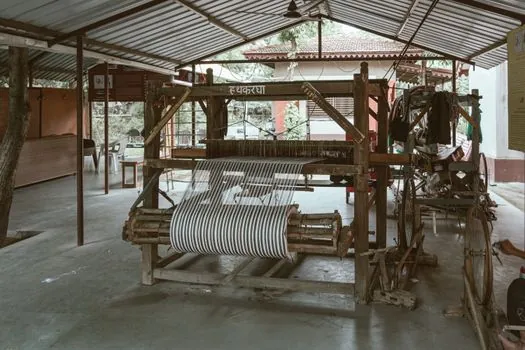
Misalignment in a textile drive comes from three sources: thermal growth of the motor frame under VFD load, base-plate deflection on a multi-storey concrete slab, and piping strain from the air-handling duct pushing on the motor stool. A close-coupled SX or SXC package handles about 0.5-1.5 per disc pack, while a spacer (SX/DI) package lifts total angular capacity to about 1.5-3.0 by stacking two disc packs in series [S1].
Parallel offset (radial misalignment) is only absorbed when there are two flex planes (i.e. a spacer design), so a single-disc-pack SU or SXC type is for angular and axial only, and a two-disc-pack SX, DI, or SXCST type is required where the motor and gearbox shafts cannot be held within 0.05 mm of perfect coaxiality [S1]. Axial end-float capacity is set by the disc-pack bolt circle and shim stack, typically 1-3 mm per pack, which covers thermal growth of a 75 kW induction motor cold-to-hot.
For a maintenance-friendly choice on long spacer drives, a split-spacer design (SXCS or SXCST) lets a mill fitter swap a worn disc pack without shifting the hubs off the shafts, cutting a typical change-out from a half-day to under two hours [S1].
Speed, balance, and API-610 for VFD-driven cards
Modern cards and ring frames are increasingly driven by VFDs in the 50-100 Hz output range, which pushes coupling speed into the 3,000-3,600 rpm band for 2-pole motors. Lovejoy publishes API-610 balance and piloting compliance up to 3,800 rpm on its disc couplings, with the unitized disc pack acting as the balance reference feature [S1].
For VFD service, the torsionally rigid, zero-backlash disc design also avoids the torsional vibration amplification that elastomer-spider couplings can introduce when the VFD carrier frequency beats against spider natural frequency; the disc pack is effectively a stiff spring, so resonance is well above running speed [S2].
Where a mill is feeding a boiler feed-water pump or a compressor off the same motor room, switching to a disc coupling brings the additional benefit of API-610 8th-edition anti-flail compliance when using DI drop-in spacer designs, which is now standard language in many EPC specs even outside oil and gas [S1].
Side-by-side comparison: disc vs gear vs jaw in a textile mill
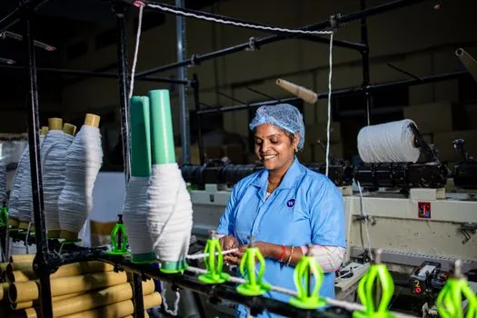
On four decision criteria a mill engineer typically weighs, the disc coupling lands as follows: (1) maintenance, zero grease versus quarterly grease for gear and 12-24 month spider change-out for jaw [S2][S7]; (2) lint/dust tolerance, all-metal sealed unit versus exposed grease cavities and open elastomer that absorb fly [S1][S3]; (3) max continuous speed, 3,800 rpm for disc versus 3,600 rpm for elastomer jaw and typically 4,000-6,000 rpm for gear [S1][S7]; (4) torque density per mm of bore, disc and gear are similar while jaw is roughly 30-50% lower for the same envelope [S2][S6].
Where a disc coupling is NOT the right answer: very high shock loads on a press drive (a flexible tyre-type coupling absorbs transients better), very low-speed indexing applications under 100 rpm where a jaw coupling is cheaper, and any installation where a coupling guard cannot be fitted, since textile-mill safety practice expects a guard on every rotating coupling regardless of type.
Spec lines for a mill RFQ
A defensible mill-side RFQ for a disc coupling should pin down, at minimum: (a) nominal and maximum continuous torque in Nm, (b) service factor applied (typically 1.5-3.0), (c) bore diameter with keyseat per ISO 773 or metric, (d) operating speed in rpm and balance grade (API-610 8th is a common baseline), (e) ambient and surface temperature rating, (f) disc-pack material (AISI-301 stainless is the industry default), (g) ATEX zone rating if solvent or dyestuff handling is in scope [S1][S3].
Also fix the spacer length as a discrete part number rather than as a drawing call-out, since OEM catalogue spacers are balanced as a matched set with the hubs; a field-modified spacer breaks balance and voids the API-610 compliance claim [S1]. For wet-process and bleach lines, specify ATEX-certified lines (SU, SX, DI, SXC, SXCS, SXCST, DIR, DILR, DIRA, DIRLA on Lovejoy) and require the disc pack to be replaceable as a unitized assembly rather than as individual shims [S1].
Cross-reference the coupling selection with adjacent safety and control spec work in the mill, for example Emergency Stop Selection for Food Processing: ISO 13850, IP Rating, and Stop Category when the same line handles food-grade textile packaging, so E-stop category, IP rating, and coupling-guard interlock logic all match at the line level.
Limitations and what to verify on site
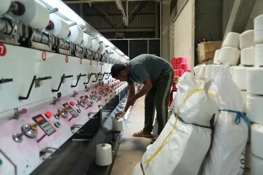
Disc couplings are not field-repairable below the unitized-pack level: when a disc pack fatigues, the entire pack is replaced, so a mill should stock at least one spare disc pack per coupling size in the plant, matched to the OEM part number and bolt pattern [S1][S3].
Alignment procedure still matters: a disc coupling is a precision component, and even with 1.5 per pack of angular capacity, running above 0.5-0.75 sustained angular offset will halve disc-pack fatigue life according to the cross-flexing rule (U = theta / theta_allow) used in the [S5] disc-coupling analysis; laser alignment on a shimmed baseplate is the standard practice for any new install or coupling change-out.
Finally, the disc pack is the wear part, not the hubs; bolting a disc pack to a non-OEM hub saves money but voids the API-610 balance claim and typically the ATEX certification, so insist on unitized packs from the original manufacturer and keep the matching hub part numbers on the BOM.
For the relevant spec sheets and selection criteria, see coupling clutch.