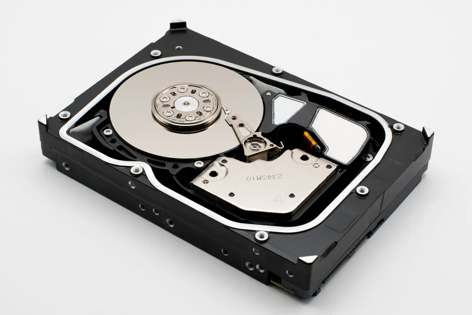
Electric actuators convert electrical energy into controlled mechanical motion and split into two primary motion families: rotary (shaft turns) and linear (straight push/pull), with further subdivision by drive mechanism and valve interface [S1][S2].
Within rotary units, gear-driven, direct-drive, and stepper variants each carry distinct torque, accuracy, and cost trade-offs that drive selection on quarter-turn and multi-turn valve packages [S1]. For valve-mounted work, the term "quarter-turn" (typically 0-90 degree) and "multi-turn" describe the output stroke, not the actuator family, and both can be served by electric drives [S1][S4].
Rotary Electric Actuators: Drive-Train Subtypes
Rotary electric actuators deliver angular motion through three common drive trains, each with a defined operating envelope [S1]. Gear-driven units use a reduction gearbox between the motor and output shaft, producing high torque output and suiting heavy-duty valve and damper service where mechanical advantage matters more than speed.
Direct-drive rotary actuators eliminate the gearbox and couple the motor shaft straight to the output, trading torque headroom for faster response and higher positioning accuracy; this topology shows up where step response and repeatability dominate the duty cycle [S1]. Stepper motor rotary actuators index in discrete steps and are specified when absolute angular positioning is the controlling parameter, accepting lower continuous torque in exchange for open-loop position repeatability [S1].
For valve interfaces, rotary electric actuators are the default drive for ball, plug, and butterfly valves, where 90 degree travel defines the work envelope, while multi-turn gearboxes extend electric rotary drives to gate and globe valves requiring many shaft revolutions [S4].
Linear Electric Actuators: Rod-Style, Rodless, and Drive Variants
Linear electric actuators convert motor rotation into straight-line motion, and the subdivision hinges on how the load is carried and what mechanism links motor to thrust rod [S2][S5]. Rod-style actuators extend and retract a rod from an enclosed housing, with the load either attached to the rod or pushed/pulled by it; the sealed housing geometry is the reason most rod-style units carry high IP ratings against water and contaminant ingress [S2].
Rodless actuators carry the load on the actuator body via an internal belt or screw rather than a protruding rod, which gives them a smaller footprint for an equivalent stroke, eliminates rod bending/buckling risk, and supports higher moment loads; this format dominates packaging, cutting, assembly, and electronics manufacturing lines [S2]. The motor-to-thrust conversion itself splits into screw-driven (high force, high precision via lead/ball screw), belt-driven (high speed, long stroke, lower force), and solenoid (short, fast, on/off strokes via electromagnetism) [S1].
Geometrically, parallel-mount linear actuators sit alongside the load, while right-angle ("L" shaped) units fold the motor drive 90 degrees relative to the stroke axis to fit constrained envelopes [S5].
Quarter-Turn vs Multi-Turn: Valve-Interface Classification

Beyond motion family, electric actuators are classified by the number of shaft rotations the driven valve requires, which dictates whether a gearbox is internal to the actuator [S4]. Quarter-turn actuators deliver roughly 90 degree rotation, sized for ball, plug, and butterfly valves, and usually include an internal override handwheel for manual operation during power loss [S4].
Multi-turn actuators turn the output shaft through many revolutions to drive rising-stem valves such as gate and globe valves; this is the class specified when the valve stem must translate linearly through the full face-to-face distance rather than rotate a disc 90 degrees [S4]. Linear-stroke electric actuators (often called "linear electric actuators" in valve catalogues) push a stem directly without rotation, suiting globe, gate, and pinch valve geometries [S4].
Selection here ties to the criteria listed in the Assured Automation actuator training: valve type, available power, environment, fail-safe need, cycle life, duty cycle, actuation speed, and manual override requirement, in that order [S4].
Electric vs Pneumatic vs Hydraulic: Comparison Matrix
Each actuator power medium trades a different set of attributes, and a simple comparison makes the choice auditable at the spec review [S1][S2][S4].
Criterion 1, power source: electric actuators run on AC or DC voltage with no compressed air or hydraulic supply needed, while pneumatic units need compressed gas infrastructure and hydraulic units need oil flow at typically 100-3000 psi working pressure [S2].
Criterion 2, control precision: electric actuators (especially stepper and direct-drive rotary, plus screw-driven linear) offer the highest positioning accuracy, pneumatic units deliver moderate repeatability, and hydraulic units lead on force density but trail on positional precision without closed-loop servo add-ons [S1][S2].
Criterion 3, operating cost and maintenance: electric units cost more upfront but are described as "far less costly to operate" than pneumatics, with no air leaks to chase; pneumatic systems are cheaper to buy but consume compressed air continuously, and hydraulic systems demand pump, seal, and fluid maintenance [S2].
Criterion 4, environment and hazard area: electric actuators are preferred in clean rooms, indoor, and explosion-risk areas where compressor exhaust is unwanted, and modern EX-rated enclosures allow deployment in hazardous zones per ATEX/IECEx frameworks; pneumatic actuators remain common in heavy industrial settings and where the existing air supply makes conversion uneconomic [S1].
For an encyclopedic overview of the broader electric actuator class, the electric actuator entry collects the cross-vendor spec vocabulary used in the rest of this article.
Selection Criteria and Limits Engineers Actually Apply
A practical selection starts with three numeric gates: required torque (rotary) or thrust (linear), stroke length or rotation angle, and duty cycle expressed as cycles per hour or percent ED [S1][S4]. Rod-style linear actuators are the right pick for end-to-end positioning, high speeds, and high force with the load either pushed or pulled; solenoid actuators are restricted to short, fast on/off strokes and lack proportional control [S1][S2].
Environmental gates are non-negotiable: outdoor or washdown service typically demands IP65 or higher on rod-style units, while hazardous-area process plants require EX-rated enclosures and certification to ATEX 2014/34/EU or IECEx schemes; named certification numbers should be cross-checked against the project hazardous-area classification before purchase [S2].
Integration gates include available supply voltage (24 VDC vs 110-230 VAC), bus protocol (on/off, 4-20 mA, HART, Foundation Fieldbus, PROFIBUS PA, or IO-Link for smaller linear units), and need for fail-safe action (spring-return or battery-backup) when loss of power must move the valve to a safe position [S2][S4]. The reference solenoid coil installation rules walk through the IP, duty cycle, and wiring gates that overlap with solenoid-class electric actuators, useful when specifying the on/off sub-family.
Failure Modes, Limits, and Common Misapplications
Electric actuators fail in characteristic ways that map back to the drive subtype, and specifying the wrong one is the most common procurement error [S1][S4]. Gear-driven rotary units overheat in high-cycle service when the gearbox is undersized for the duty cycle, while direct-drive rotary units stall mechanically rather than thermally, with less warning time.
Linear rod-style actuators leak past the rod seal first; the IP rating is only as good as that seal, and a high IP housing with a worn rod wiper is a common field failure [S2]. Belt-driven linear units stretch over time and lose stroke repeatability, so they should not be specified where positional accuracy drifts below 0.1 mm over a multi-year maintenance interval.
Solenoid electric actuators are frequently misapplied in proportional-control service, where the on/off nature of the solenoid cannot deliver intermediate positions without PWM or closed-loop control electronics added downstream [S1]. Stepper rotary actuators lose steps under transient overload without an encoder to flag the fault, so they are not the right pick where stall-induced position error is a safety hazard.
For valve work, mismatching a quarter-turn electric actuator to a multi-turn rising-stem valve is a recurring procurement error: the actuator simply cannot produce the many shaft revolutions required, regardless of torque rating [S4]. A linear electric actuator wired to a rotary ball valve is the symmetric mistake, and is usually caught at mechanical commissioning rather than the desk review.
Standards, Sourcing Signals, and What to Track

The standards that govern electric actuator specification in process and valve service include ATEX 2014/34/EU and the IECEx scheme for hazardous-area enclosures, ISO 5211 for actuator-to-valve mounting interface dimensions, and EN 15714 (Industrial valves: actuator selection and sizing for valves) for the sizing methodology itself; NACE MR0175 applies when the driven valve handles sour-service hydrocarbons, and API 6D references gate, ball, and check valves in pipeline service [S1][S4].
On the supply side, actuator pricing has stayed range-bound through 2025-2026, with lead times for gear-driven rotary units and multi-turn valve actuators running 8-14 weeks on standard configurations and longer on EX-rated or custom-stroke builds. One trackable signal is EN 15714-2 revision activity for electric actuator sizing, which is the document most procurement teams cite when they challenge a vendor's torque/thrust margin; another is the roll-out of IO-Link on smaller linear actuators, which is changing the wiring topology of low-power machine-building electric actuators away from discrete I/O.
Track these for the next sourcing cycle: ATEX/IECEx certificate numbers for hazardous-area units, ISO 5211 mounting flange code (F03/F05/F07/F10/F12/F14/F16), duty cycle rating in starts-per-hour or percent ED, and the explicit ambient temperature range, typically -20 to +70 degrees Celsius for general-purpose units and -40 to +85 degrees Celsius for low-temp or desert installations.
The underlying component specifications are covered under lighting equipment and electric lamps.