An electric motor production line is, at its core, a discrete-assembly cell chain whose takt time is set by the slowest station, not by the winding machine. Requirement engineering literature treats the specification sheet as the gate that prevents downstream rework [S2][S4].
The line is structured around three sub-lines: a stator line (core stamping, winding, insulation, impregnation), a rotor line (shaft machining, magnet or cage insertion, balancing), and a final assembly line (end-shield fit, bearing press, terminal connection, no-load and locked-rotor test) [S3]. The decision that most often decides throughput is the cell vs. linear-line choice at the rotor sub-assembly step.
Requirement engineering must precede cell sizing
Specifying requirements explicitly is the first step in any motor design or manufacturing exercise, and large OEMs publish their own specification forms to enforce this [S2]. The WEG specification guide formalises the inputs the line must accept, including frame size (e.g. IEC 80 to IEC 315L), thermal class (B, F, or H), enclosure (TEFC, ODP, TEFC-IP55), and ambient/corrosion zone (C2 inland, C3 urban-industrial, C4 coastal/food-processing) [S1].
Decision criteria that must be locked before cell takt is calculated: rated voltage and frequency (220-380 V / 50-60 Hz, dual-frequency 50/60 Hz), duty cycle (S1 continuous through S9 intermittent), power factor and efficiency class (IE3, IE4, IE5 per IEC 60034-30-1), and starting method (DOL, star-delta, VFD). Without these numbers in writing, cell balancing becomes guesswork and station count inflates [S1][S2].
Stator line: from lamination stack to impregnated winding
Stator lamination stacks are typically built from 0.35-0.5 mm silicon steel, welded, interlocked, or bonded, with stack heights chosen to hit the design magnetic flux. Winding stations fall into three families: needle winding for stators up to roughly 80 mm stack height, flyer winding for mid-range frames, and injection or hairpin winding for EV traction motors, which raise copper fill factor above 60% [S3].
Insulation class F (155 deg C) is the volume default for industrial motors, with class H (180 deg C) reserved for inverter-fed or high-ambient applications; WEG specifies thermal class F as standard on most IEC metric frames [S1]. Varnish impregnation (dip-and-bake, VPI, or trickle) follows insertion, and the choice between trickle (cycle time 30-90 s per stator) and VPI (batch, 2-6 h cycle) directly sets the buffer size between winding and assembly cells [S3].
Rotor line: shaft, cage or magnet, and balancing
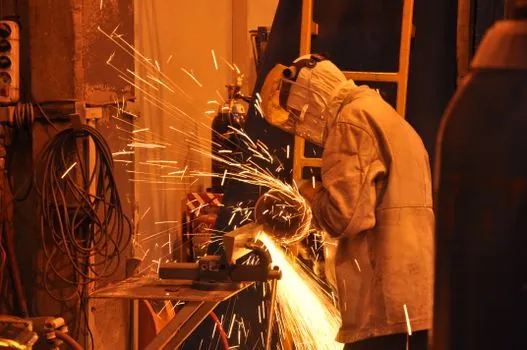
Squirrel-cage rotors use die-cast aluminium cages injected at 700-750 deg C into a closed slot stack, while slip-ring rotors add a commutator assembly step. Permanent magnet rotors for PMSM lines require magnet insertion (surface-mount, interior, or V-shape), magnetisation after assembly to limit handling risk, and a non-magnetic sleeve or carbon-fibre wrap on high-speed rotors [S3].
Balancing grade is specified per ISO 1940-1: G2.5 for general-purpose industrial motors, G1.0 for fans and pumps, and G0.4 for precision spindles. The balancing cut is one of the few operations on the line that cannot be parallelised easily, and the throughput bottleneck of the rotor sub-line is almost always either die-cast or dynamic balance, depending on the lot mix [S5].
Cellular assembly vs. linear conveyor: a criteria comparison
Cellular assembly groups all operations for one motor family in a U-shaped or parallel station cluster, with one operator handling 3-5 stations; this is the dominant architecture for low-mix, mid-volume runs of 50,000-300,000 units per year [S5]. Linear conveyor with pallet transfer suits high-mix lines and re-sequencing, at the cost of higher fixture count.
Decision matrix for assembly architecture: takt time under 30 s favours linear conveyor with automatic torque tools; takt time 30-120 s favours cellular with one operator per 3-5 stations; takt time above 120 s and high variant count favours cell with AGV-routed pallets. Changeover time on a cellular cell for a frame-size swap is typically 5-15 min, against 30-90 min for a linear line re-tool, which decides the answer when SKU count exceeds roughly 20 variants [S5].
Final test, terminal connection, and the IE-class gate
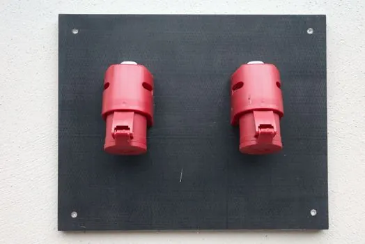
Terminal connection is the last electrical step before the test cell: lead wires from the stator winding are crimped or bolted to the terminal block, and the connection scheme (star/delta) is set on the terminal board, not hard-wired in the stator [S3]. The test cell then runs no-load (to measure current, speed, and noise), locked-rotor (to measure starting current and torque), and a high-pot test on the winding insulation.
For IE3/IE4/IE5 motors, the test cell must include a torque-controlled dynamometer capable of loading the motor to 100-150% rated torque, and the efficiency calculation follows IEC 60034-2-1 methods (summation of losses, or direct input-output with uncertainty below 0.5%). Stations that did not exist in IE2 lines, like low-voltage VFD test stands for sensorless vector verification, are now mandatory in the IE5 retrofit wave documented in adjacent spec-first retrospectives on electric motor Industry 4.0 adoption [S1].
Failure modes that drive the next design iteration
The three failure modes that consistently show up in motor line ramp-up are: (1) insulation class creep, where a motor spec'd to class B ends up running at class F temperatures because the cell skipped a thermal-rise test, (2) bearing press force drift, where unmonitored hydraulic presses begin seating bearings partially and re-work shows up at 1,000-3,000 hours of field life, and (3) rotor imbalance from a balancing machine whose calibration cycle exceeds lot size, usually visible only at the OEM's noise-and-vibration test [S3][S5].
Standard references for the spec-driven retrofit wave and capacity sizing live in the encyclopedia: electric actuator for the motion-control cousin of the motor assembly line, and electric pallet truck for the AGV-routed pallet flow that ties cells together on a modern motor plant floor.
Trackable signals for the next planning cycle: a publicly indexed capacity model for 2027 IE5 volume, per the Electric Motor Production Capacity Planning: 2026 Spec Map reference, and a published IE5 efficiency curve envelope that cell test stands can be sized against before the next capex round.
Spec-level background on the components involved: electric ball valve.