
A process control loop around an electric motor uses a sensor or transmitter, a controller comparing measured value to setpoint, and a final control element such as a variable-speed motor or motorized valve [S1]. Standard three-phase induction motors with frame sizes 56 to 355+ are specified to IS 12615:2018 for output ratings from 0.12 kW to 1000 kW at voltages up to 1000 V and 50 Hz, on S1 continuous duty [S3].
On the control side, the dominant architectures are direct-on-line (DOL) starters, soft starters, and variable-frequency drives running scalar V/Hz or vector control, each trading start-up torque, speed range, and cost differently [S2][S5]. Closed-loop position control is a textbook example: a motor-driven globe valve uses a potentiometer wiper on the stem as feedback, with the controller comparing that voltage to a reference to set valve position [S4].
Loop Anatomy: Sensor, Controller, Final Control Element
The minimum viable motor control loop has three nodes. A sensing element (PSE) or transmitter reads the process variable, the controller subtracts setpoint and computes a manipulated variable, and the final control element (FCE) physically changes the plant, for example a variable-speed electric motor, a control valve, or an electric heater [S1]. The manipulated variable is the controller output sent to the FCE [S1].
For motorized valves, position feedback is often a potentiometer wiper on the stem giving a voltage proportional to stem travel; this feedback is fed to the amplifier controlling the motor and compared to a reference voltage so the reference directly sets valve position [S4]. Sensor accuracy, controller sample time, and FCE dead time together define loop bandwidth, and mismatched bandwidth is the most common root cause of hunting in motor-driven positioning loops.
Starter and Drive Topologies: Selection Criteria
Three starter topologies cover the bulk of industrial fixed-speed and variable-speed work, and selection is driven by starting torque, mechanical stress tolerance, and whether closed-loop speed control is required [S5].
DOL starters provide simple on/off control with overload protection and are the lowest-cost option for small pumps and fans where start-up torque is not limiting [S5]. Soft starters ramp voltage up and down to limit inrush and mechanical shock, extending belt, gearbox, and coupling life on conveyors, large fans, and pumps [S5]. Variable-frequency drives add closed-loop speed and torque control, and within VFDs the scalar V/Hz method keeps the voltage-to-frequency ratio constant to hold magnetizing flux near rated value across the speed range, at the cost of slower dynamic response versus vector control [S2].
Scalar V/Hz is "particularly interesting when there are multiple motors connected to a single drive," because the drive does not need per-motor current feedback to estimate rotor flux [S2]. Vector or field-oriented control is preferred where fast torque and speed response matter, for example extruder screws, hoists, and high-dynamic tension stands.
Who VFDs, Soft Starters, and DOL Are For (and Not For)
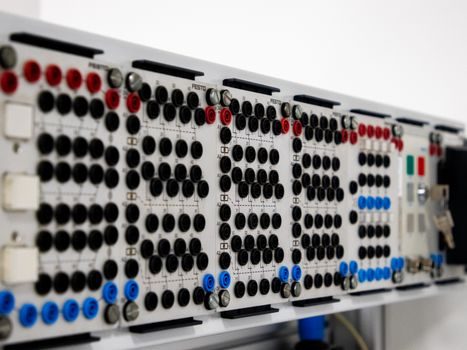
DOL is the right call only for small fixed-speed loads where the utility feed can absorb locked-rotor inrush (typically 5 to 7 times rated current for a few seconds) and the driven equipment tolerates the start transient [S5]. It is the wrong call for anything that suffers from water hammer, belt slip, or gearbox shock on a hard start.
Soft starters are for fixed-speed processes that still need a gentle start: large centrifugal pumps, long conveyors, crushers, and fans [S5]. They do not save energy at steady state and they cannot trim speed for process trim, so a process that needs turndown belongs on a VFD instead.
VFDs are the right tool when turndown exceeds roughly 20%, when flow or pressure must be modulated by speed rather than throttling, or when the process benefits from soft start plus adjustable acceleration. They are not the right tool for very slow shafts driving gear reducers with high ratio, because VFD carrier frequency, bearing currents, and gearbox resonance can interact badly; a sine filter or output reactor is the usual mitigation.
Frame Sizes, Ratings, and What IS 12615:2018 Actually Covers
The Indian standard IS 12615:2018 sits over three-phase squirrel-cage, totally enclosed, air-over induction motors in 2, 4, 6, or 8 poles, with output ratings from 0.12 kW to 1000 kW at rated voltage up to and including 1000 V and 50 Hz [S3]. Frame sizes run from 56 up to and including 315M as specified in Table 3 of IS 1231, then 315L with declared output, then 355 and above per IS 8223 [S3]. Duty class is S1 continuous; S2 and higher duty cycles are covered when an equivalent S1 output is declared [S3].
For buyers, this means three concrete spec gates before issuing a PO: frame-to-output correlation per IS 1231, declared efficiency class (IE2/IE3/IE4 as applicable), and a sampling plan that the supplier can meet. Inspection levels per Table 1 of the EESL inspection manual call for dimensional checks on IS 1231/IS 2223/IS 2254 every 200 motors, earthing per IS 3043 on every motor, and momentary excess torque per IS 15999 (Part 2/Sec1) every 50 motors of the same type and design [S3].
Instrumentation Around the Motor: Sensors, Signals, and Failure Modes

Modern motor control rarely ends at the starter. The most common field-side instruments are current transformers (CTs) for overload and phase-loss, thermistors or RTDs in the winding for thermal protection, vibration sensors on the bearing housing, and shaft encoders or resolvers for closed-loop speed and position [S1]. Each of these is a separate sensor node feeding back into the controller or a dedicated protection relay.
Three failure modes show up repeatedly in field service. First, mismatched bandwidth: a 50 ms temperature loop cannot stabilize a process that is being agitated every 200 ms by a VFD switching cycle. Second, ground loops and EMI: VFDs generate common-mode voltage on the motor cable that couples into 4-20 mA loops and encoder wiring; shielded twisted pair with proper single-point grounding is the standard mitigation. Third, sensor placement: a motor-mounted vibration sensor reads bearing housing, not rotor bar condition, and a thermal sensor embedded in the end-winding reads the hotspot the insulation class is actually rated for, while a surface-mounted RTD reads the frame and lags by 10 to 15 minutes. Engineers who skip this last distinction end up undersizing or oversizing motors.
Standards, Sourcing Signals, and What to Watch Through 2026
The standards that govern motor process control are layered: efficiency and rating (IS 12615:2018 for India, IEC 60034-30-1 for IE classes globally), frame dimensions (IS 1231, IS 2223, IS 2254, IS 8223), protection (IEC 60079 series for Ex zones, IS 3043 for earthing), and instrumentation (ISA-5.1 symbology, IEC 61131-3 for PLC programming) [S3]. Any quote that does not state frame, IE class, duty, insulation class, and IP rating is incomplete.
For sourcing, three signals are worth tracking through 2026. First, the convergence of VFDs and soft starters: many modern soft starters now include a bypass contactor and basic PID, blurring the line. Second, the rise of integrated motor-drive units, where the VFD is mounted on the motor frame to cut cabinet space and cabling, and where the relevant spec gate becomes the combined IE class of the system, not just the motor. Third, the demand pull from IE3 and IE4 minimum-efficiency regulations, which is forcing panel builders to re-spec DOL and soft-starter panels to VFDs for part-load energy savings. For buyers, the practical move is to keep frame and duty specification tight, name the controller and feedback standard explicitly, and require a loop diagram, not just a one-line.
Buyers comparing process control options should also track adjacent spec territory: a loop calibrator price and cost guide for 2026 helps instrument shops size maintenance budgets, while the multistage centrifugal pump suppliers 2026 map helps plant engineers match pump and motor specs at the same time. For panel design, the transformer OEM vs ODM spec-driven decision map covers the upstream power side that feeds the motor center, and a magnetic drive pump spec map covers leak-tight process loads where the driven equipment matters as much as the motor.
Component reference pages worth checking: multifunction process calibrator, v process line, and electric actuator.
Related analysis: Decade Resistance Box Selection Guide: Range, Accuracy, and Cal Use.