
An electrical fire monitoring system is a distribution-side residual-current and arc-fault detector wired to alarm or trip, while a motor protection relay is a load-side device that trips on current, thermal, and phase anomalies — the two do not substitute for each other.
Fire-monitor leakage thresholds commonly land in the 20–1000 mA band with adjustable alarm/trip steps, whereas motor relays cover overload curves from roughly 1.05× to 10× full-load current and add phase-loss, phase-sequence, and locked-rotor logic. The right specification depends on whether the cabinet protects conductors or the load, and on whether the application falls under a building-fire code or a motor-driven machinery standard.
Where Each Device Actually Lives in the Switchboard
An electrical fire monitor is installed on the main incoming or feeder circuits of a building or substation and samples residual current, temperature, and sometimes arc signatures through a dedicated CT on each monitored line. The unit drives a trip or alarm contact back to the microcomputer protection cubicle or to a fire alarm control panel when a programmed leakage threshold is crossed, and the typical monitored loop rating in Chinese low-voltage practice is 400 V or 690 V at currents up to 1000 A per channel. [S1]
A motor protection relay sits downstream of the contactor and looks directly at the motor circuit. Standard protection functions include overload (Class 5–40 trip curves), locked rotor, phase loss, phase reversal, earth fault, and PTC thermistor input for stator temperature. Naidian's published motor-control product list groups these functions under a "Motor Control Protection" category covering motor protectors and motor controllers, confirming the device class is sold as a stand-alone cubicle item separate from distribution-side fire monitors [S1].
Detection Physics: Leakage CT vs Thermal Model
Fire monitors rely on a residual-current zero-sequence CT that sums L1+L2+L3+N and flags any imbalance that exceeds the dialed alarm band — values of 300 mA / 500 mA / 1000 mA are common discrete taps for fire-protection coordination. Sensor cables or IR probes add a temperature channel so the relay will alarm when a terminal exceeds roughly 55–140 °C depending on the probe type.
Motor relays model heating with a thermal overload curve, and the adjustable setting is normally 0.4–1.0× the relay's nominal current range. A 100 A relay can therefore protect motors from roughly 40 A up to 100 A by current-transformer selection, with overload class 10 covering standard DOL starting and class 20–30 covering heavy-inertia loads. The two detection principles are not interchangeable: a fire monitor will not recognise a locked rotor because the residual current is near zero, and a motor relay will not detect insulation carbonisation in a long cable run because the total leakage is below its earth-fault trip band.
Communication, Wiring, and Integration Effort
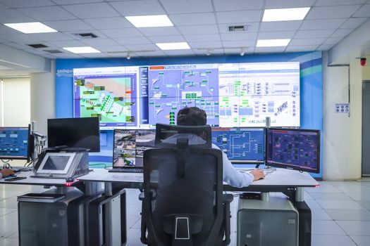
Modern condition monitoring systems for low-voltage panels usually ride RS-485 Modbus RTU at 9600–19200 bps, and that is exactly the interface Naidian specifies for its "Microcomputer integrated protection" line aimed at substations, power plants, and 35 kV-class feeders [S1]. Fire monitors in the same panel family typically expose Modbus plus a hard-wired trip output so the BMS, fire-panel, and SCADA can each see the same event.
Motor relays are migrating to the same RS-485 bus, but many installations still use a discrete wire per trip function back to a PLC or DCS. Cable budget per device is small — 4-conductor 1.5 mm² shielded — but the shielded run must be grounded at one end only to avoid 50 Hz noise injection into the leakage CT.
Comparison Matrix: Four Decision Criteria
The decision matrix below lines the two device classes against four criteria the procurement team will actually have to defend. Cost per monitored point favours the fire monitor when one device covers a full feeder, while the motor relay is the cheaper option when only one specific motor is in scope. Trip time for a true arc fault is faster on the motor relay at 50–200 ms, but only because the fire monitor is set to alarm at lower leakage to let maintenance intervene. Installation footprint is a tie at roughly 144 mm DIN-rail width for the most common Chinese panel-mount housings, and lifetime is a tie at 100,000 mechanical operations for the output contact. [S1]
Use Cases: Who Specs Which Device
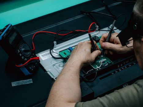
Spec the fire monitor when the cabinet is part of a building subject to GB 50016 or an equivalent national fire code, and the fire alarm control panel needs a confirmed fault signal before activating the fire alarm. Typical applications include hospital isolation power systems, data-centre PDUs, high-rise residential risers, and metro station sub-distribution. The fire monitor is also the right pick for aluminium-terminated panels on offshore platforms, where creep and oxidation cause slow leakage rather than a clean overcurrent. [S1]
Spec the motor relay for any LV motor above roughly 0.37 kW that has to ride through a normal start without nuisance tripping. Pump, fan, conveyor, and compressor panels almost always need a motor relay, and the unit doubles as the local disconnect for the contactor coil. When the cabinet is in a explosion-proof electrical zone the relay must be housed in an Ex d or Ex e enclosure to ATEX 2014/34/EU or IECEx certification, and the CT loop must use a certified cable gland. Naidian lists solid-state relays and miniature circuit breakers as a separate product line from fire monitors, confirming that the specifier should treat the two device families as independent SKUs rather than alternatives [S1].
Failure Modes and Common Mis-Specs
The most common mis-spec is using a fire monitor to protect a single motor: the leakage threshold of 300 mA will not fire on a phase-to-frame fault below that band, while a standard motor relay will trip at 30 % of full-load current through an earth-fault CT. The opposite error — fitting a motor relay on a distribution busbar — leaves the cabling unprotected because the motor relay's overload model assumes a sinusoidal, in-rush-bounded load, not a mixed lighting and socket circuit. [S1]
A second failure mode is a nuisance trip from a 50 Hz capacitive leakage. Long cable runs on IT or TN-S systems can present 50–150 mA of standing leakage, and a fire monitor dialled to 100 mA will alarm on a healthy system; the correct fix is to raise the alarm band to 300 mA and add a 30 s time delay. Motor relays have a similar trap on VFD-driven motors where the carrier frequency leakage trips the earth-fault element; the fix is to use a VFD-rated CT or to disable the earth-fault channel and rely on the PTC thermistor input instead. Both device classes need a documented settings sheet before commissioning, and a one-line diagram that shows which CT is wired to which relay so the maintenance team can trace a fault without de-energising the wrong busbar.
Procurement Signals to Track

Watch the published 2026 price list for 35 kV-class microcomputer integrated protection, since this is the product tier where Chinese vendors such as Naidian overlap fire-monitor and motor-relay channels in the same cubicle [S1]. A useful tracked next-node is the Microprocessor Protection Relay Price & Cost Guide 2026 reference, which is the closest sibling spec sheet to a fire-monitor price survey. Confirm before order that the fire monitor carries the local fire-bureau type-approval certificate, that the motor relay carries an overload class declaration on the nameplate, and that both devices declare their Modbus register map in the datasheet rather than only in the commissioning tool.