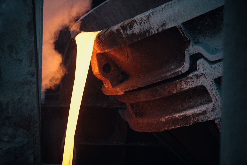
Liquid steel from either route feeds continuous casting machines at 1–6 m/min casting speed, with slab/bloom/billet section sizes set by end-product: 200–250 mm thick slabs feed plate/strip mills, 100–150 mm blooms feed beam mills, and 100–200 mm round/square billets feed bar and seamless pipe lines [S1].
Primary Steelmaking: BOF vs EAF Route Comparison
EAF furnaces in the 80–200 t range melt scrap or DRI using 400–700 kWh/t electric input with a tap-to-tap cycle of 35–60 min, and can be powered by renewable grids where green-steel programmes are funded.
Use of EAF stainless-steel flat products has grown because decarburisation via AOD or VOD works at lower scale than BOF for high-chromium grades.
Continuous Casting and Secondary Metallurgy
Secondary metallurgy — ladle furnace, RH degasser, and wire-feed station — is the step that actually sets final chemistry before casting; inclusion control, hydrogen below 1.5–2.0 ppm for heavy plate, and sulfur below 0.005% for linepipe grades are routine targets [S1]. Continuous casters run curved-mould or vertical-bending designs; thin-slab casters cast 50–90 mm slabs direct into a tunnel furnace for hot-strip mills, while conventional slab casters feed 200–250 mm slabs through a reheat furnace at 1200–1250 °C.
Cast-strand defect types — surface cracks, central segregation, and pinholes — are governed by mould oscillation frequency (100–400 cpm) and secondary-cooling water at 0.8–1.5 L/kg-steel [S1]. These are the same defect modes that drive ultrasonic testing in downstream pipe lines, discussed below.
Hot Rolling, Cold Rolling and Finishing
Plate mills roll 5–150 mm plate for shipbuilding (ASTM A131), pressure-vessel (ASME SA516), and linepipe (API 5L X65–X80) applications, using accelerated cooling (Accu-Therm / Q&T) to hit yield-strength and toughness targets.
Bar and rod mills produce 5.5–50 mm rebar and wire rod at 100–120 m/s finishing speed on a 10-stand no-twist block; section mills (heavy) roll beams, channels, and rails with a 1500–1900 mm roughing stand and a universal reversing mill [S1]. For electrical steel, final grain orientation happens in a decarburising anneal at 820–850 °C under HNX atmosphere — relevant to the silicon-steel grade family used in transformer cores and EV traction motors.
Pipe and Tube Production Line
Spiral welded pipe mills on the [steel pipe production line](https://www.txhmachine.com/) form 219–2540 mm OD pipe at 6–25 mm wall from hot-rolled coil, with submerged-arc welding (SAW) wire feed at 2.5–4.0 m/min welding speed and ID/OD bead removal integrated; high-frequency welded (HFW) lines cap out at 610 mm OD and run at 30–80 m/min, with seam annealing to restore parent-metal properties at the weld line [S2]. Hydraulic testing stations pressurise pipe to 1.5–2.0× design pressure (commonly up to 25 MPa for linepipe) and hold 5–30 s; ultrasonic testing arrays at the line exit detect 0.5–1.0 mm wall-laminations, while X-ray gear inspects ERW seam integrity for sour-service grades [S2].
Anti-corrosion lines wrap 3LPE/3LPP (epoxy + adhesive + polyethylene/polypropylene) coating at 1.5–2.5 mm thickness and inline apply FBE (fusion-bonded epoxy) at 200–250 °C powder melt for water and crude pipelines; insulated-pipe lines add PUR foam 30–80 mm jacket for district heating and offshore flowlines [S2]. Sizing, chamfering, and hydrostatic test benches complete the line; for seamless pipe, the Mannesmann piercing mill + mandrel mill route sits in a separate steel-mesh-free plant fed by round billet casters.
Quality Control, Standards and Testing Discipline
For sour-service linepipe, hardness caps at 22 HRC and the alloy-steel grades drop Cr-Mo-V to limit cracking susceptibility.
Ultrasonic and eddy-current arrays (to ASTM E213 / E309) replace dye-penetrant on many ERW/HFW welds because they catch volumetric defects; the same logic is increasingly applied to steel-fiber cut lines, where automated eddy-current tracks per-wire tensile strength at 200 m/min [S1][S2]. Plant acceptance for dimensional tolerance follows ISO 4200 (plain-end steel tube) and API 5L (linepipe); mill test certificates carry heat-number traceability back to the caster strand.
Process Limits, Failure Modes and Selection Cues
Continuous-casting cracks are the single biggest cost driver in plate and pipe scrap; the fix is mould-level control at ±3 mm and secondary-cooling water flow 0.8–1.5 L/kg, with soft-reduction at the final solidification point [S1]. Cold-rolled strip edges crack on too-tight a coiler tension at gauge below 0.3 mm, and the fix is tension-level control plus 5–15% temper-pass elongation; EAF route is more variable on residuals (Cu, Sn, Cr) and limits automotive exposed-panel quality unless DRI/HBI dilutes the scrap pool.
Pipe-line failure modes split into seam defects (HFW/ERW seam porosity, SAW slag inclusion) and body defects (laminations from slab inclusions). Both are caught by combined hydrostatic + ultrasonic testing; pipe lines running above 100 m/min on the mill typically deploy phased-array UT heads downstream of seam annealing [S2]. Beyond this, route selection, caster capacity, and finishing-mill mix remain the three concrete levers a buyer or specifier can interrogate on the data sheet rather than on the marketing brochure.
For a parallel take on how spec bands and supplier tiers are read in adjacent heavy industries, the Top Bearing Companies 2026: Supplier Tiers, Spec Levers and Sourcing Reality piece applies the same yardsticks to forging buyers. Process engineers spec'ing BF–BOF and EAF routes against the same end-product should track caster tap weight and ladle metallurgy capability, plus pipe-line NDT throughput in m/min as a real productivity marker on the data sheet.