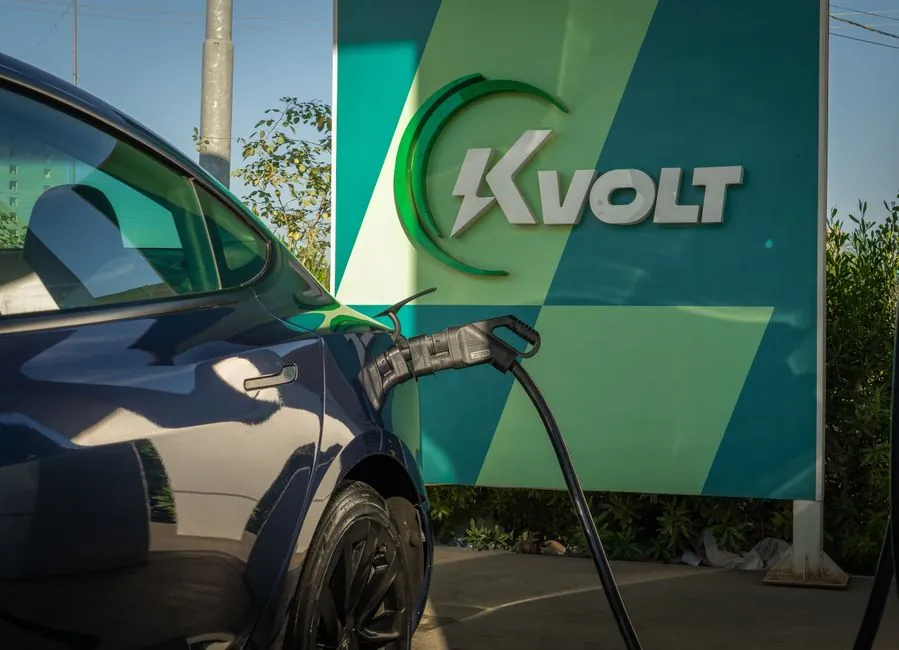
End-of-line test cells for off-board DC EV chargers now routinely execute four non-negotiable gates: (1) SECC/EVCC protocol handshake with fault injection, (2) full-load efficiency and power-factor measurement, (3) OCP/OVP/thermal protection verification, and (4) leakage-current and ground-fault checks, with production tact times targeted at 5-15 minutes per unit depending on coupler count [S1][S5].
Current DC fast-charger production lines cover outputs from 30 kW modules up to 350 kW+ public units, span four connector families (CCS, NACS, CHAdeMO, GB/T) and must clear communication protocols codified across IEC 61851-1, IEC 62196 series, SAE J1772, CHAdeMO 1.2/2.0, GB/T 27930, plus OCPP 2.0.1 for back-office conformance [S1][S2][S4].
Communication Handshake Test: SECC vs EVCC, Inlet Simulation
The first failure mode on a DC EVSE line is communication-side, not power-side: if the Supply Equipment Communication Controller (SECC) and Electric Vehicle Communication Controller (EVCC) desynchronize on timeout, data format, or timing, the charging session is forcibly terminated, so production ATE must simulate the EV inlet, including electronic lock, temperature monitoring, and high-power contactor [S1].
Modular EV simulators with interchangeable charging inlets are now standard practice because they cut swap time when a station is in an abnormal state, and they let one test cell cover CCS, NACS, CHAdeMO, and GB/T without rewiring [S1]. Fault injection at the protocol layer is used to verify the EVSE's interruption protection fires correctly on a malformed ParameterDiscovery or PowerDelivery message [S1].
Multi-Coupler Stations: Parallel Emulators and Test Throughput
Modern DC fast chargers ship with two or three couplers (for example CCS1+CHAdeMO, or CCS2+AC Type 2), so the test cell must drive multiple EV emulators in parallel rather than running them sequentially, which would otherwise add minutes per cycle and break the production tact time [S1].
Recommended architecture pairs each EV emulator with its own battery simulator and shared test software, allowing real-time loading of charging-current profiles so the EVSE's closed-loop response time and current-accuracy can be measured against the dynamic demand of the simulated pack [S1]. Throughput targets in published Chroma references sit in the 5-15 min/coupler band, with a three-coupler station therefore requiring roughly 15-45 min of active test time before final QA [S1].
Power Quality, Efficiency, and Power Factor
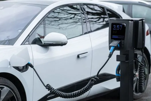
Standby power consumption, power factor, and DC-side charging efficiency are explicit DC EVSE test items on production ATS platforms, with power-meter accuracy class and bandwidth chosen to capture the wide operating range from idle (<100 W typical) to rated output [S1].
For AC and DC chargers combined, third-party test labs now publish coverage from residential 3.3 kW units to high-power public fast chargers, reflecting the market spread that any OEM EOL strategy must absorb [S4]. Output ripple and noise on the DC bus, plus transient response to a step load, are documented as standard electrical-performance gates for off-board chargers and are typically captured with an oscilloscope and a programmable electronic load [S5].
Protection Verification: OCP, OVP, Thermal, and Ground Fault
Protection verification is the safety gate that determines ship/no-ship: overcurrent protection (OCP) trip thresholds, overvoltage protection (OVP) on both AC input and DC output, thermal protection at the connector and power-module level, plus residual-current and ground-fault detection, all run as scripted test steps before the unit leaves the cell [S5].
Leakage-current measurement at the AC input, ground-bond continuity, and electrical-isolation resistance are tied to UL 2231 (personnel protection) and IEC 61851-1 (general conductive charging system safety), with the EV simulator and battery simulator absorbing the energy of any intentional fault so the unit under test is not damaged during verification [S1][S2][S5]. For comparison against typical dynamic load behavior, the brake-resistor heat-dissipation trade-off discussion of energy absorption hardware is a useful cross-reference for how a test cell handles worst-case regen or fault energy.
Standards Stack That Drives the Test Plan
EVSE test plans are anchored on a layered standards stack: IEC 61851-1 for the conductive charging system, IEC 62196 series for plugs/couplers, IEEE 1547 and IEC 61000-series for grid interconnection and EMC, SAE J1772 and SAE J3400 for AC/DC signaling (including NACS), CHAdeMO for the Japanese DC protocol, GB/T 27930 for the Chinese DC protocol, UL 2231-1/-2 for personnel protection, and OCPP 2.0.1 for back-office interoperability [S2].
Tektronix-cited scope for an EVSE safety/compliance lab explicitly bundles connector, communication, grid/power-quality, and safety compliance testing into four pillars, which maps one-to-one onto the four ATE gates above and is the de facto checklist used by third-party labs and OEM EOL cells alike [S2][S4]. The relevant lamps and lighting test fixtures reference explains how a similar four-pillar approach (electrical, photometric, EMC, safety) is structured for a different product family, and is useful framing for cross-industry test engineers reviewing the EVSE plan.
Where the Line Cell Differs from a Type-Approval Lab
Production EOL is a go/no-go gate, not a characterization lab: the goal is to catch build defects (wrong firmware, miswired contactor, OVP setpoint drift, ground-bond fail) at line speed, with test points selected so a single failure can be re-tested within the same tact window, while full EMC, environmental, and type-approval work is reserved for the certification lab [S3][S5].
This is why battery-pack EOL, discussed in the UNICO/MCC webinar on cell/module/pack manufacturing (March 2025), uses high-rate pulse formation and end-of-line cyclers with regenerative DC buses rather than a full laboratory cycler, and the same cost-driven logic is now visible on the EVSE side as the move to modular, parallel EV emulators and shared battery-rail simulators in the test cell [S3]. Mechanical-handling parallels appear in the molding line reference, where cycle-time discipline and per-station fault containment drive the same trade-off between test depth and throughput.
Limits, Failure Modes, and Open Signals to Track
The documented failure modes that a 2025-spec EOL cell must still catch are: SECC/EVCC timeout or malformed-PDU desynchronization, dual-coupler cross-talk, power-factor or efficiency drift outside the data-sheet envelope, OCP/OVP/thermal trip-threshold out of spec, and ground-fault/leakage-current out of UL 2231-1/-2 limits, all of which Chroma and VVDN reference as recurring production escapes without scripted ATE [S1][S4][S5].
Signals worth tracking through the next two quarters: (1) OCPP 2.0.1 conformance test-suite rollouts from the Open Charge Alliance, which will push more back-office interoperability checks into EOL; (2) the migration of NACS from SAE J3400 to a fully IEC-aligned coupler spec, which is forcing a second generation of EV simulator modules; and (3) ISO 15118-20 (Plug & Charge 2.0) conformance tooling, which adds a PKI/certificate check to the SECC/EVCC handshake that no current ATE platform covers out of the box. For grounding philosophy on the test bench itself, the common-point ground bonding reference applies to the EOL station's safety-ground topology in the same way it does for any high-power electronics assembly.
Spec-level background on the components involved: tensile testing machine.