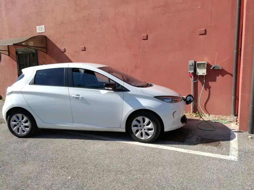
An EV charging station production line pairs a sheet-metal enclosure line with a power-module sub-assembly, a control-PCB functional test cell, and a final pack-out station; modular conveyor staging with RFID pallet tracking is the layout most OEMs adopt for mixed AC Level 2 and DC fast-charger builds [S1][S2].
Design choices for the line, ranging from Level 1, Level 2, and DC fast-charge variants, enclosure material, ISO 15118 communication, and end-of-line testing, drive the station count, takt time, and floor space of any new EVSE plant [S3][S5].
Process Stations and Typical Cycle-Time Bands
A standard EVSE line runs seven core workstations: bottom-cover loading, enclosure welding or sheet-metal fabrication, power-module assembly (contactors, residual-current devices, and a 7–22 kW AC or 30–360 kW DC stack), control-PCB mounting with M3/M4 self-tapping screws, HMI and display fitment, cable-harness routing, and end-of-line test plus packaging [S1].
For an AC Level 2 (SAE J1772 / IEC 61851-1 Mode 3) charger, the per-unit cycle time at a semi-automated cell typically lands in the 8–12 minute band, with a manual takt of about 15 minutes for residential SKUs [S2]. DC fast-charger cabinets, where the power-module stack alone weighs 40–80 kg, usually drop to a 20–30 minute per-unit cycle when sub-assemblies are pre-staged on a conveyor sorting line [S1][S2].
Communication and Grid-Integration Modules
ISO 15118 governs the bidirectional vehicle-to-grid (V2G) protocol between EV and charger, and OCPP 1.6/2.0.1 governs the backhaul to the charging station network, so the control-PCB station must provision both stacks on a Sitara-class or equivalent Linux-capable application processor [S3].
For commercial units, an OCPP-managed backend with cellular or Ethernet backhaul is the default; residential units increasingly piggyback on home Wi-Fi and ISO 15118 plug-and-charge credentials stored in the on-board HSM [S3]. Design teams that under-spec the comms module, for example omitting the HSM or the secure-boot chain, typically retrofit it within 18–24 months as V2G and OCPP 2.0.1 conformance tightens, which inflates field service cost.
Enclosure, Power, and Safety Subsystems
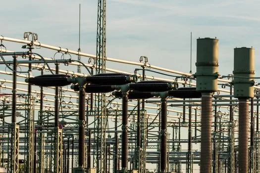
Rittal's specification guide for designing electric vehicle charging stations discusses how specifying standard enclosures and parts can speed up the design and production process.
Inside the cabinet, a Level 2 AC charger carries AC and DC residual-current detection, an isolation barrier, contactors with coil drivers, energy metering ICs, and a user-interface display, with a 7 kW single-phase and a 19.2 kW / 22 kW three-phase as the dominant power ratings [S3]. DC fast chargers add a 30–360 kW SiC or IGBT stack, liquid-cooling plates on a 50/50 water-glycol loop, and a CCS1/CCS2/CHAdeMO/GB/T connector head, which is the most labour-intensive sub-assembly in the line.
Line Layout: Modular Conveyor vs Fixed Cell
SDC's semi-automated assembly system for EV charging hardware uses a modular conveyor spine, RFID-tracked pallets, and dedicated test cells, which lets the same line build three to five SKU variants without retooling [S2]. A fixed-cell layout, by contrast, costs 15–25% less in capex but loses roughly 10 points of overall equipment effectiveness (OEE) when SKUs change over [S2].
Plants targeting an annual output above 50,000 AC units or above 5,000 DC units generally justify a modular molding line spine and a dedicated automatic molding line for connector housings; below those volumes a U-shaped fixed cell with a 4–6 person manual takt is more capital-efficient [S1][S2].
End-of-Line Test and Quality Gates
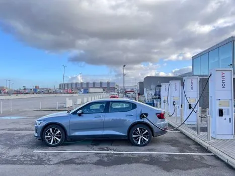
Every EVSE unit must pass a four-step end-of-line gate: hipot / ground-bond at 2,500 V AC for 1 second, a 4–20 mA loop and OCPP handshake verification, a residual-current device trip test at 30 mA / 6 mA DC, and a 30-minute burn-in at full rated load [S1][S3].
For DC fast chargers, the burn-in is performed at the full 30–360 kW rating, which forces a separate high-bay test cell with a 400–800 V DC electronic load and a chilled-water return, and typically bottlenecks the line at 2.0–2.5x the AC takt time [S1]. The decision criteria for AC vs DC end-of-line cells is straightforward: AC units need a 1.5–3.0 kW test bay per station, DC units need a 50–500 kW regenerative DC load and a grid interconnect sized at 0.4–1.0 MVA per test position.
Selection Map: Who Should Build What
New entrants with under 10,000 units/year of planned output should buy standard enclosures and contract the power module, then assemble the control PCB and HMI in-house; this path matches the spec-guide recommendation and is what most North American Level 2 OEMs have done since 2023 [S5]. Plants targeting 50,000+ AC units or 5,000+ DC units/year should own the full modular conveyor sorting line, the end-of-line burn-in, and the OCPP/ISO 15118 stack [S2][S3].
Volume BOM-cost economics for the same set of choices are covered in EV Charging Station Manufacturing Cost: BOM, Drivers, and Margins, which pairs the line-design decisions above with bill-of-material sensitivities.
Trackable signals for the next planning cycle: UL 9741 and IEC 61851-1 conformance test throughput at the end-of-line cell, residual-current device false-trip rate in the first 90 days of field operation, and OCPP 2.0.1 firmware update roll-back rate, each of which feeds directly back into the line's takt-time and station-count assumptions.