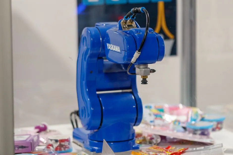
A machine vision system for manufacturing is the combination of an industrial camera, matched optics, engineered lighting, a processing platform and inspection software that captures images on a line and turns them into pass/fail or dimensional data in milliseconds, replacing manual inspection at full production throughput [S2][S6].
Typical deployments hit 100% inspection coverage at line speed, with camera resolutions scaling from 8.3 MP all-in-one AI units up to 20 MP edge devices, and the buy decision now hinges on lighting design, sensor type (CMOS vs CCD), and protocol support for PLCs and MES rather than raw image quality [S3][S4][S7].
Core Components and What Each One Actually Does
Every production vision cell is built from six functional blocks: illumination, industrial camera (image sensor), optics/lens, frame grabber or direct GigE/USB3 interface, computing platform (industrial PC, embedded GPU, or smart camera), and the processing software that runs the inspection [S6][S8][S10].
Camera choice follows the line: 2D area-scan cameras handle standard part inspection and code reading, 3D cameras deliver depth maps for robot guidance and surface profiling, and line-scan cameras cover continuous webs such as paper, film, textile, sheet metal and nonwoven substrates [S1][S3].
Optics set the field of view, depth of field, and working distance; matching lens focal length and aperture to the part and conveyor speed is the single biggest source of avoidable scrap, which is why integration guides treat lighting and optics as a single engineering task, not a parts list [S1][S7].
Traditional Rule-Based vs AI-Powered Vision
Rule-based (classical) machine vision relies on thresholding, edge detection and template matching; it is fast and deterministic but requires precise, repeatable lighting and breaks when part appearance drifts [S3][S4].
AI-powered vision, almost always deep-learning classifiers or detectors, trains from labelled examples, tolerates natural part variation, and exposes a no-code browser interface where quality engineers can re-train a defect class with as few as 5 reference images in under an hour [S3].
The economic case in factory QA is documented at roughly 75% reduction in inspection cost and 50% reduction in rework after AI vision rollouts, with deployment dominated by edge-processed smart cameras (e.g. 8.3 MP and 20 MP all-in-one units with integrated NVIDIA GPU) rather than rack PCs in a control room [S3].
The four buying criteria that separate a fit-for-purpose AI cell from a sunk-cost project are: (1) edge processing to keep latency and IP inside the plant, (2) native industrial protocols (EtherNet/IP, PROFINET, Modbus TCP, OPC-UA, MQTT) for PLC/MES hand-off, (3) code-free training for the QA team, and (4) integrated or guided lighting rather than a generic ring light [S3].
Selection Criteria by Inspection Task
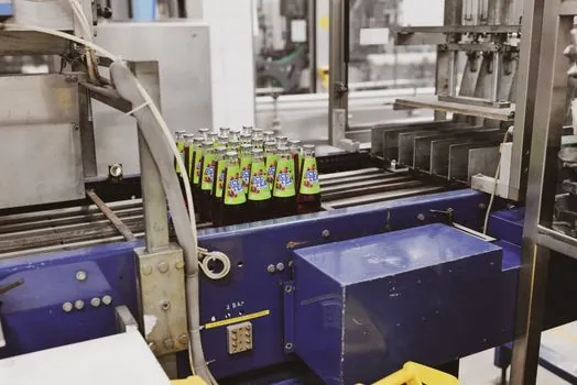
Surface defect inspection (scratches, dents, discoloration) on reflective metal or painted parts is where AI vision clearly beats classical vision, because deep models generalise across gloss, curvature and texture variations that defeat fixed thresholding [S3][S4].
Dimensional measurement and tolerance checks still pair well with rule-based tools when edges are crisp and lighting is controlled; a hybrid cell, where AI does defect classification and classical tools do metrology, is the common 2026 architecture on EV battery and electronics lines [S3][S7].
Code reading (1D/2D/DataMatrix) and OCR are dominated by purpose-built 2D smart cameras; pick-and-place and weld guidance are dominated by 3D vision feeding robot pose data over PROFINET or EtherNet/IP, and the deeper coverage of vision-system architecture is mapped in the machine vision system reference page.
Where Machine Vision Fits, and Where It Does Not
Machine vision is a fit for: 100% inline inspection at line speed, repeatable dimensional checks, presence/absence verification, code and label reading, and robot guidance in high-mix or high-volume cells [S1][S4][S5].
It is not a fit for: defects that are not visually detectable (subsurface cracks, internal porosity), low-volume or high-SKU runs where one-off programming cost exceeds the labour saving, and unstable ambient lighting that cannot be enclosed, all of which are flagged as common failure modes in vendor implementation guidance [S1][S5].
It is also the wrong tool when the inspection tolerance is below the optical resolution of the chosen sensor/lens pair, or when a process change is being used to escape the defect instead of detecting it; vision should never be specified as a substitute for a stable process [S1][S7].
Lighting, Sensors, and Resolution: The Spec Triad
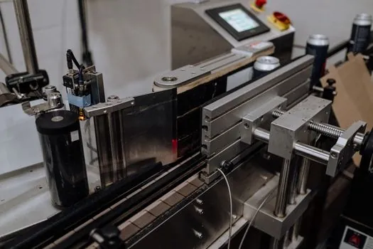
Sensor technology choice matters: CMOS dominates modern industrial cameras because of higher frame rates, lower power and on-chip analogue-to-digital conversion, while CCD remains relevant in very-low-light or scientific imaging where global shutter uniformity and noise floor still lead [S4][S10].
Resolution is set by the smallest defect (in mm) divided by the field of view (in mm), multiplied by the number of pixels the algorithm needs across that defect, typically 4-8 pixels per feature for rule-based tools and 32+ pixels for reliable deep-learning detection [S1][S7].
Lighting is selected to maximise feature contrast: backlight for silhouette and dimensional checks, diffused dome light for shiny or curved surfaces, dark-field ring or coaxial light for scratch and engraving detection, and structured light (laser line or pattern projector) for 3D profiling [S1][S3][S7].
Specific component families, such as smart cameras, line-scan modules, and the identification side of machine vision, are catalogued in the machine vision id encyclopedia entry, which complements the system-level overview linked above.
Integration with PLCs, Robots and MES
A vision cell only delivers ROI when its pass/fail signal closes a control loop: a discrete reject output or a fieldbus write to a PLC, a robot pose update over PROFINET or EtherNet/IP, and an inspection record pushed to the MES for batch traceability [S1][S3][S4].
Frame grabbers and interface choice matter for bandwidth: GigE Vision and 10 GigE Vision are now standard for multi-camera lines, USB3 Vision survives on single-camera cells, and CoaXPress remains the choice for very-high-speed line-scan at multi-MHz pixel rates [S1][S10].
For 2D dimensional metrology cells that share staging with linear and crossed-roller motion hardware, the vision measuring machine reference page covers the multi-axis staging and encoder feedback that bridge a vision system to a coordinate-measuring workflow.
Standards, Sourcing, and What to Track Next
No single ISO or IEC standard covers an entire machine vision system; instead, system integrators work to sector rules such as ISO 9001 quality management, IEC 62443 for industrial network security, and application-specific standards (e.g. FDA 21 CFR Part 11 for pharma, IATF 16949 for automotive suppliers), while camera and interface conformance is governed by standards bodies including the AIA (GigE Vision, USB3 Vision, CoaXPress) and EMVA (EMVA 1288 sensor characterisation) [S1][S4].
Trackable signals worth watching through 2026: continued shift of inference from PC-based vision to edge smart cameras with on-board GPU, the migration of vision data off the line and into MES/ERP via OPC-UA over TSN, and the convergence of AI defect detection with classical metrology inside the same cell. For sourcing context, the additive manufacturing material reference covers how vision is increasingly used to inspect 3D-printed parts, which is one of the faster-growing 2026 use cases. Related factory-automation context, including power and supply decisions that sit next to any vision cell, is in the programmable DC power supply spec-anchored selection guide.